Open topic with navigation
1. Configuring Analog and Digital Trunks
If you have analog or digital trunks, you need to configure those trunks in Wave before you can use them.
The base level configuration of the Wave IP 500 Server and Wave IP 2500 Server include two and four analog trunks respectively. Adding digital or additional analog trunks requires that the appropriate modules or cards be installed in the Wave Server. For more information, see the Wave Server Installation Guide.
Trunk configuration tasks include:
|
•
|
Creating new trunk groups. |
|
•
|
Modifying the default trunk groups to meet your specific requirements. |
|
•
|
Creating outside line-enabled trunk groups. |
|
•
|
Configuring trunks and channels. |
Note: Before you configure trunk groups, trunks, and channels, be sure you understand the concepts presented in Understanding Wave Trunks
About trunk groups
Before you can configure analog and digital trunks and put them in trunk groups, those trunk groups must exist. Wave provides default trunk groups (see the Default trunk groups table) that you can use to quickly group a set of analog or digital channels for most call routing scenarios.
You can:
|
•
|
Rename the default trunk groups to be more meaningful to your business or call-routing scenarios, for example, "Connect to PBX", "Long Distance Calls", "ISDN", and so forth. |
|
•
|
Modify the default trunk groups to meet your specific requirements. |
|
•
|
Create new trunk groups, if the default trunk groups provided with Wave do not meet your needs. |
|
•
|
Create outside line-enabled trunk groups. |
You create additional trunk groups according to the steps in Creating a new trunk group. Those steps describe how to create, name, and set the direction and hunt order for a new trunk group. Later in the configuration process, you will configure Caller ID settings on the Out tab (see Configuring Caller ID) and configure the In tab (see Configuring trunk groups for inbound call routing).
About creating outside lines
Creating a new trunk group
Deleting a trunk group
Trunk groups
Configuring trunks and channels
Configuring trunk-specific Caller ID settings
Configuring trunk groups for inbound call routing
About creating outside lines
You can map an Outside Line button on a digital phone directly to one or more trunks, simulating a key system.
Note: In Wave ISM, the term “outside line” specifically refers to this digital phone feature—throughout the Wave documentation, another term, “external line”, is used when referring to the common action of pressing a specific button (typically 9) on any type of phone to get dial tone to make an external call.
Important! Calls made or answered via an Outside Line feature button on a phone do not appear in the ViewPoint Call Monitor because ViewPoint does not know about Outside Line feature button call activity.
Setting up outside lines consists of the following tasks:
|
•
|
Create an outside line-enabled trunk group using the Trunk Groups applet. |
Note: One of the settings you specify when you create an outside line-enabled trunk group is whether it is a single-call variant or multiple-call variant outside line. The variant type determines how outside line buttons on digital phones are associated with the trunks in the trunk group.
|
•
|
Associate physical trunks with the outside line-enabled trunk group using the Trunk Configuration applet. |
|
•
|
Add Outside Line buttons to users’ digital phones in either of the following ways: |
|
•
|
User Configuration (Templates) applet. Create or edit the feature button assignments in a digital phone template via the Feature Button Configuration dialog. Feature button assignments made via templates are applied to all users assigned that template. For details, see Configuring phone templates. |
|
•
|
User/Group Management applet. Configure the phone features for an individual user’s digital phone via the User dialog Phone \ Station Features tab. Feature button assignments made via the Station Features tab apply only to that user’s phone. |
Outside lines
Creating a new trunk group
Configuring phone templates
Creating a new trunk group
To create a new trunk group
|
1
|
If necessary, click the Administration tab of the Management Console. |
|
2
|
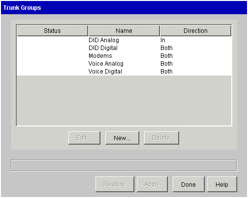
Click Trunk Groups, located in the Trunk Administration section. |
|
3
|
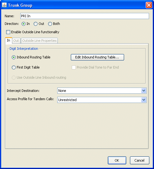
Click New to create a new trunk group. The Trunk Groups dialog opens. |
|
4
|
At the top of the dialog, enter the following information: |
|
•
|
Name. Enter a name or phrase for the new trunk group, using up to 16 alphanumeric characters. This trunk group name will appear on Caller ID phones when calls are received via this trunk group and no Caller ID was received. |
Note: You can give a trunk group any meaningful or descriptive name. You might want to include “Trunk Group” in the name, for example “Voice Digital Trunk Group”, to differentiate trunk groups from routing tables that might have the same or similar names.
Hint: Wave automatically identifies an outside line-enabled trunk group when it displays the trunk group’s name in other applets (for example, Trunk Configuration) by prefixing the trunk group’s name with “OL|”. You may want to indicate in an outside line-enabled trunk group’s name whether it is a Single Call or Multiple Call variant outside line (selecting a variant is described in the following procedure.) This will make it easier later on to identify the trunk group and its qualities when you configure the trunks associated with the trunk group, via the Trunk Configuration applet.
|
•
|
Direction. Select In, Out, or Both to specify the direction of the trunk group. Your Service Confirmation Letter should detail the direction of your installed trunks—refer to it to determine which direction to select here. |
Individual service providers may use different terms to describe trunk direction for voice circuits, for example:
|
•
|
“In”, “inbound” (with respect to the Wave Server) |
|
•
|
“Out”, “outbound” (with respect to the Wave Server) |
|
•
|
“Both”, “bidirectional”, “two-way”, “2-way”, “in and out” |
|
•
|
If you are configuring the trunk group with Outside Line functionality, select the Enable Outside Line functionality checkbox to create an outside line-enabled trunk group. Note that selecting this checkbox enables the Outside Line Properties tab as well as the Use Outside Line Inbound Routing setting on the In tab. |
|
5
|
If this trunk group will be used for inbound calls, click the In tab to specify how inbound calls are to be handled. |
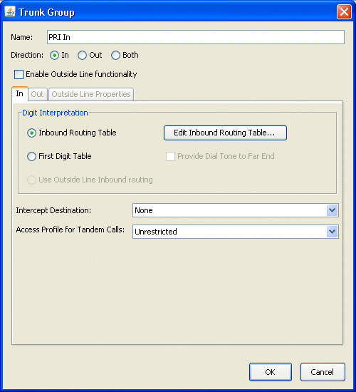
See Configuring trunk groups for inbound call routing for information on how to use the fields on this tab.
|
6
|
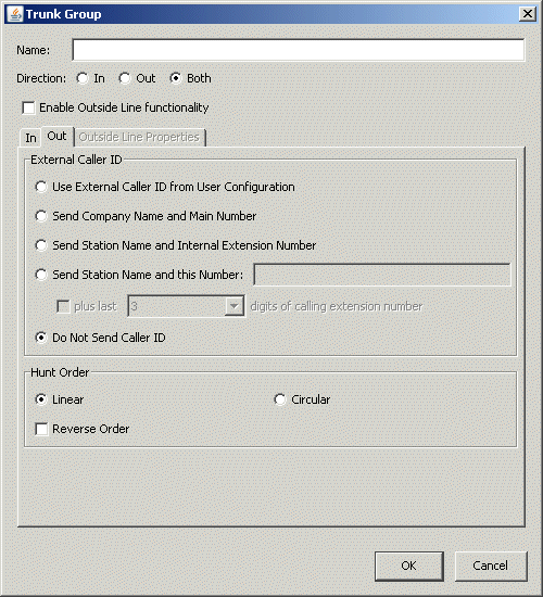
If this trunk group will be used for outbound calls, click the Out tab to specify how outbound calls are to be handled. |
|
7
|
In the External Caller ID section, specify how to provide Caller ID for outbound calls: |
|
•
|
Use External Caller ID from User Configuration. Select this option to send the information specified for the user as entered in the User/Group Management applet. (Unless modified for an individual user, this will be the default information specified in the General Settings applet.) |
|
•
|
Send Company Name and Main Number. Select this option to send the Company Name and Main Number, as entered in the System tab of the General Settings applet. |
Note: Although Company Name can include up to 16 alphanumeric characters, be aware that no more than 15 Caller ID characters can be sent over an ISDN trunk.
|
•
|
Send Station Name and Internal Extension Number. Select this option to send the Station Name, as entered in User/Group Management applet. |
|
•
|
Send Station Name and this Number. Select this option to send the Station Name (as entered in User/Group Management applet) followed by the digits you enter. (Use this setting to provide station name and number on outbound calls.) |
In addition, if you select the plus last ___ digits of calling extension number checkbox, the specified number of digits from the calling extension are appended to the digits you entered.
|
•
|
Do Not Send Caller ID. Select this option if you do not want to provide external Caller ID. |
|
8
|
In the Hunt Order section, select one of the following: |
|
•
|
Linear. Looks for a free channel, always starting at the beginning of the list of trunks in the trunk group and searching to the end, or—for reverse-order hunting—always starting at the end of the list and searching to the beginning. |
|
•
|
Circular. Looks for a free channel, starting where the last search left off. From this point (where the last search left off), forward-order hunting works forward through the list of available channels, and reverse-order hunting works backward through the list. |
For either hunt order type, select the Reverse Order checkbox as applicable.
For more information about hunt order types, see Trunk group hunt types.
|
9
|
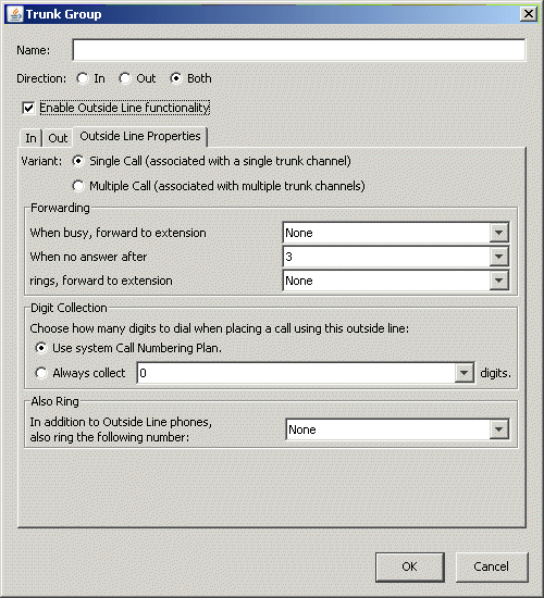
If you selected Enable Outside Line functionality to create an outside line-enabled trunk group, click the Outside Line Properties tab. |
|
10
|
Specify the Variant, one of two ways in which outside line buttons on digital or SIP phones will be associated with the trunks in this trunk group: |
|
•
|
Single Call. Select this option (the default) to associate each outside line with a single trunk. If lit, the light next to the outside line button on a user’s digital phone indicates if the trunk is in use by any phone. |
|
•
|
Multiple Call. Select this option to associate each outside line with multiple trunks. If lit, the light next to the outside line button on a user’s digital phone indicates if all of the associated trunks are in use. |
Warning! Once you select a Variant and click Apply or Done in this dialog, if you want to change the variant you must first deselect the Enable Outside Line functionality checkbox, click Apply, make the change, and then re-select Enable Outside Line functionality.
For more about Single Call and Multiple Call variants, see Outside lines.
|
11
|
In the Forwarding section, specify the forwarding options to be applied to inbound calls on this outside line: |
|
•
|
When busy, forward to extension. Select the extension to which an inbound call will be forwarded when all associated outside line buttons are busy with other calls. If you select None (the default), the caller will hear a busy signal. |
|
•
|
When no answer after. Select the number of rings (up to 9) to wait before forwarding an unanswered inbound call to the extension specified in the next field. |
|
•
|
rings, forward to extension. Select the extension to which an unanswered inbound call will be forwarded after the number of rings specified in the previous field. If you select None (the default), associated phones will ring indefinitely. |
|
12
|
In the Digit Collection section, choose how many digits to dial when placing outbound calls on this outside line: |
|
•
|
Use system Call Numbering Plan. Select this option so that the system will determine how many digits to wait for depending on the first digits dialed. For example, under the North American Numbering Plan, if a user dials a 1, the system waits for 10 more digits before sending the number to the central office. |
|
•
|
Always collect __ digits. Select this option to require the user to enter the specified number of digits when placing a call on the outside line. |
|
13
|
In the Also Ring section, select any extension or station hunt group to be rung along with associated digital phones on an inbound call. |
|
14
|
When you are done creating or editing the trunk group, click OK to save your changes and close the Trunk Group dialog. |
|
15
|
Click Done to close the Trunk Groups applet and return to the Management Console. |
Deleting a trunk group
About creating outside lines
Outside lines
Configuring trunk groups for inbound call routing
Configuring trunk-specific Caller ID settings
Trunk group hunt types
Configuring trunks and channels
Deleting a trunk group
You cannot delete a trunk group that is still in use in the current configuration. If you attempt to do so, Wave identifies the conflicts that must be resolved before you can complete the deletion.
To delete a trunk group
|
1
|
If necessary, click the Administration tab of the Management Console. |
|
2
|
Click Trunk Groups, located in the Trunk Administration section. |
|
3
|
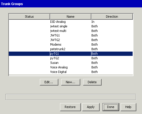
Select one or more trunk groups and then click Delete. |
|
4
|
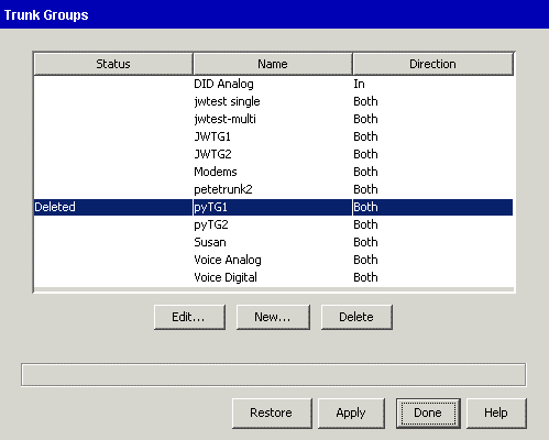
The Status for the Trunk Group changes to Deleted. |
|
5
|
When you have no further changes to make in the Trunk Groups applet, click Done. Click Yes when you asked if you want to save your changes. |
|
6
|
If any conflicts are detected, you will observe the following depending on where the conflict exists: |
|
•
|
If the trunk group you selected is still in use in the Outbound Routing applet, the Deleted Trunk Group(s) Still In Use dialog opens, listing the locations where the trunk group is still being used. |
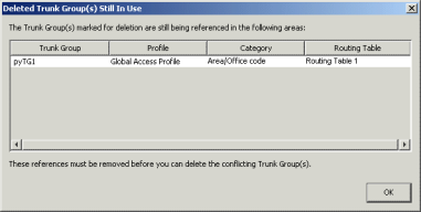
The following information is displayed for each conflict:
|
•
|
Trunk Group. Name of the trunk group that is still in use. |
|
•
|
Profile. Access profile name where the hunt group is used, for example “Global Access Profile”, “Private Network”, or custom access profile name. |
|
•
|
Category. Category within the access profile, for example Area Code Table, Off-Premise Extension Table, Special Digits Table, Privileges, and so forth. |
|
•
|
Routing Table. Name of the routing table where the conflict exists, or “None” for Privileges or Carrier Access. |
|
•
|
If the trunk group you selected is still configured for one of the external digits in the First Digit Table, the Cannot Delete Selected Trunk Group dialog opens: |
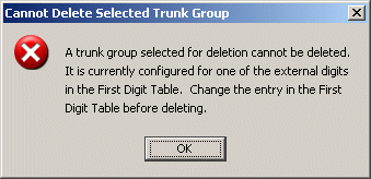
Important! Make a note of the conflicts so that you can address all of them. The trunk group in question cannot be deleted until all outstanding conflicts have been resolved.
|
7
|
Click OK. The Trunk Groups applet closes automatically. In the Outbound Routing applet, remove the trunk group in question from the configuration to resolve all identified conflicts. Then run the Trunk Groups applet again and delete the trunk group. |
Creating a new trunk group
About creating outside lines
Outside lines
Configuring trunk groups for inbound call routing
Configuring trunk-specific Caller ID settings
Trunk group hunt types
Configuring trunks and channels
Configuring trunks and channels
You use the Trunk Configuration applet to set up the handshake and signaling between the Wave Server and the equipment on the service provider end of the trunk. Using this applet, you can set the configuration options to match the settings your trunk service provider has provisioned on your trunks.
Locate your Service Confirmation Letters or provisioning information forms before starting the following procedures. See Sample trunk service confirmation letter for an example.
Caution! The trunk options and the channel/trunk signaling options must be set identically to the settings shown on your trunk Service Confirmation Letter.
Caution! Never mix trunk types within a trunk group. If necessary, create a new trunk group (see About trunk groups).
About trunk groups
Trunk and channel settings
Configuring trunks and channels
Configuring digital trunks and channels
Enabling trunks for external pager and call notifications
Trunk and channel settings
Both digital channels and analog trunks have three major configuration parameters, as described in the following table:
|
Enabled
|
Places a T-1 or analog channel or trunk into service or removes it from service.
|
|
Signaling
|
Sets the signaling method for the channel or trunk.
|
|
Trunk group (for voice or modem channels)
|
Sets the trunk group membership for the analog trunks or digital channels.
For example, you can assign a trunk group called Voice Analog to eight separate analog trunks.
|
About trunk groups
Configuring trunks and channels
Configuring digital trunks and channels
Configuring analog trunks
You use the Trunk Configuration applet to configure analog trunk settings for the analog trunk ports on the Integrated Services Card or on expansion cards and modules. Refer to your Service Confirmation Letter, provided by your service provider, for the appropriate values to set.
Before configuring the trunks, configure the trunk groups you want to assign to the analog trunks. For information about configuring trunk groups, see About trunk groups.
Caution! If you need to permanently remove an analog trunk module from your Wave Server, or replace an analog trunk module with a different module, you must first assign all ports of the module to None in the Trunk Group drop-down list in the Trunk Configuration applet. For details about this drop-down list, see step 5 of Configuring analog channels.
Complete the following tasks to configure analog trunks:
Using analog loop start trunks with mobile extensions
Using mobile extensions over trunks which do not support disconnect supervision can cause a trunk to get stuck, requiring you to disable and re-enable the trunk via the Trunk Configuration applet. This problem can occur when a user on a mobile extension connected via an analog loop start trunk puts a call on hold and goes onhook. The problem stems from the fact that the CO does not always propagate disconnects over loop start trunks, so Wave is never informed when the user goes onhook.
It is highly recommended that all analog trunks be tested for disconnect supervision by calling an external number from a Wave phone, connecting, and then having the called (external) party hang up. If the Trunk Monitor indicates that the trunk cleared before the local extension went onhook, then the trunk does support disconnect supervision and can be safely used for mobile extensions.
Configuring analog trunk card or module settings
To configure the analog trunk card or module settings
|
1
|
If necessary, click the Administration tab of the Management Console. |
|
2
|
Click Trunk Configuration, located in the Trunk Administration section. |
|
3
|
Select the card or module you want to configure, then select the Trunk in Service check box. |
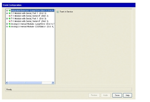
Note: If your Wave Server only has a Integrated Services Card and no other analog trunk modules, there will only be one entry in the list, Integrated Services Card - Loop Only.
Refer to the Wave Server Hardware Reference Guide for information about each card and module installed in your Wave Server.
|
5
|
Click Apply to save your changes. |
|
6
|
Click Done to return to the Management Console. |
Configuring analog channels
Customizing AC impedance settings on analog trunk ports
Configuring trunks and channels
Configuring analog channels
To configure a card or module’s analog channels
|
2
|
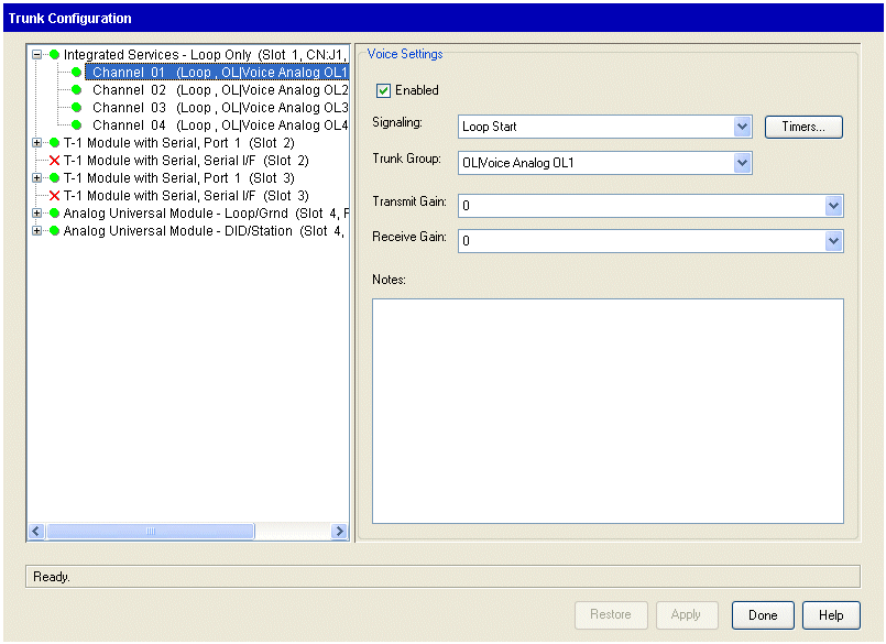
Click the + next to a card or module to display the channels, and select the channels you want to configure. |
|
•
|
To select a contiguous range of channels, select the first channel in the range, then hold down the Shift key while you select the last channel in the range. |
|
•
|
To select a noncontiguous range of channels, hold down the Ctrl key while you select each channel. |
|
3
|
Make sure that the channels are enabled—to do so, select the Enabled check box. |
|
4
|
Select the signaling method from the Signaling drop-down list. |
The signaling method is indicated on your Service Confirmation Letter. See Sample trunk service confirmation letter for an example.
The signaling methods are as follows:
|
•
|
Loop Start. This option is required if you are configuring the analog trunks on the Integrated Services Card. |
|
•
|
Ground Start. This option is available only for the Analog Universal Module and the Analog Trunk Module. |
|
•
|
Wink Start. This option is available only for the Analog Universal Module. |
Caution! Timer settings (accessed via the Timers button) are expert settings, and should not be modified unless you are instructed to do so by your Vertical Technical Support representative.
|
5
|
Select the trunk group you want to assign to the selected trunks from the Trunk Group drop-down list. |
Warning! If the trunk group you select is a Single Call variant outside line-enabled trunk group and you had previously selected more than one channel in step 2, you will see an error message similar to the following. Click OK to clear the message, and go back and select a single channel:

|
6
|
Adjust the Transmit Gain and Receive Gain values if necessary. |
|
•
|
Transmit Gain. If the voice level of outgoing calls is too low, increase the value; if the voice level is too high, decrease the value. |
|
•
|
Receive Gain. If the voice level of incoming calls is too low, increase the receive gain; if the voice level is too high, decrease the value. |
Caution! Feedback can result if you set the gain level too high. In most cases, the default value of 0 should be fine.
|
7
|
Record information in the Notes field. |
This information could include circuit-specific information or other information from the Trunk Configuration property sheet. Circuit number and carrier information or brief notes regarding issues encountered can be entered in this comment field. Field personnel can use this data to locate and identify the physical circuit connected to the Wave Server.
|
8
|
Click Apply to save your changes. |
|
9
|
Click Done to return to the Management Console. |
Customizing AC impedance settings on analog trunk ports
Customizing AC impedance settings on analog trunk ports
You can customize AC impedance settings on analog trunk ports in order to correct echo return loss problems. In cases where the echo return loss is poor, users may experience unusually loud side-tone or echo on calls over analog trunks.
Caution! These are expert settings that should not be modified unless you are instructed to do so by your Vertical Technical Support representative in order to resolve a specific analog trunk echo problem. Improper settings will degrade voice quality on calls.
To customize AC impedance settings
|
1
|
There are 2 ways to configure AC impedance settings for analog trunks: |
|
•
|
Via the General Settings applet. Use this method to customize AC impedance settings for all analog trunks, as part of the system Locale settings. On the System tab click Customize. When the Customize Locale dialog opens, click Analog Trunk Impedances. |
|
•
|
Via the Trunk Configuration applet. Use this method to customize AC impedance settings for specific analog trunks or channels. In the Trunk Configuration dialog, select one or more analog channels and then click Impedance. |
In both cases, the Customize Impedance dialog opens.
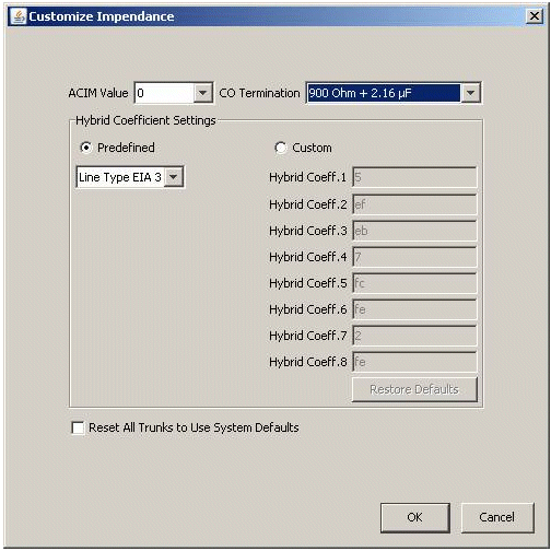
Depending on how you accessed this dialog, different default values will be displayed:
|
•
|
From the Customize Locale dialog, the defaults reflect valid combinations of pre-defined data for the selected Locale. |
|
•
|
From the Trunk Configuration applet, pre-defined system values are displayed. |
|
2
|
Specify the following information: |
|
•
|
ACIM Value. Specifies the terminating impedance that Wave analog trunks present to the CO. ACIM Value is location-specific and generally does not need to be changed. |
For North America, the correct value is 0, which sets the Wave trunk terminating impedance to 600 Ohms. Other locale-specific defaults may have different values.
Note: This value is not the same as the value displayed in the CO Termination field.
|
•
|
CO Termination. Specifies the terminating impedance that the CO presents to Wave trunk. CO Termination is associated with the ACIM Value and generally does not need to be changed. |
For some locations, there may be an alternate value that can be tried. In North America the terminating impedance presented by the CO is 900Ohms + 2.16uF. In North America the alternate CO Termination value is 600 Ohms. This alternate choice may sometimes apply if Wave is connected to a local PBX rather than directly to the CO—some PBXs provide a 600 Ohm terminating impedance instead of the standard 900ohms+2.16uF presented by the CO.
|
•
|
Predefined/Custom. Select one of the following: |
|
•
|
Predefined. Select this option to use the default hybrid coefficients based on the selected ACIM Value and Line Type. In almost all cases, this will result in acceptable performance. |
|
•
|
Custom. Select this option to define alternative hybrid coefficients in rare cases where adequate performance cannot be obtained via a predefined Line Type. |
Caution! Identifying custom hybrid coefficient values should only be done under the direction of your Vertical Technical Support representative.
|
•
|
Line Type. Specifies the length and characteristics of the 2-wire cable that connects the Wave Server to the CO. There are 8 predefined EIA line types, EIA 0 – EIA 7: |
|
•
|
EIA 0 represents the shortest cable length (under 2000 feet). |
|
•
|
EIA 6 and EIA 7 represent the longest and most complex line types. |
Note: Testing has shown that EIA 3 is an appropriate setting for most installations. In cases where EIA 3 is does not provide good performance, one of the other predefined EIA line types can usually be found to provide adequate echo return loss performance.
|
•
|
Hybrid Coeff.1 - 8. If you selected Custom above, enter a value from 0-255 in the text box for a specific hybrid coefficient. Click Restore Defaults to discard your changes and restore the default values. |
|
3
|
To discard all of your changes and revert to the pre-defined system values, select the Reset All Trunks to Use System Defaults checkbox. |
About trunk groups
Trunk and channel settings
Configuring trunks and channels
Configuring analog channels
Configuring digital trunks and channels
Configuring digital trunks and channels
You use the Trunk Configuration applet to assign voice, data, or ISDN traffic to digital channels; to configure connection settings for a digital channel on WAN modules or cards (for example, the two-port T-1 module); and to assign each channel to a connection.
Caution! If you need to remove a T-1 module from the Wave Server, you must first assign all channels of the module to None in the Connection drop-down list in the Trunk Configuration applet. For details about this drop-down list, see step 5 in “To configure the digital trunk card or module settings ,”.
After making changes to your digital trunk configuration
Note the following:
|
•
|
Courtesy vs. Forced reset: Some digital trunk and digital channel configuration changes require that you reset the affected trunks or channels for the changes to take effect. When this occurs, you are prompted to perform either a Courtesy or Forced reset. |
At the digital trunk level:
|
•
|
If you choose a Courtesy reset, changes are applied immediately if the trunk is idle. If the trunk is not idle, calls in progress are allowed to complete, but all new inbound and outbound calls on the entire span are blocked. When the entire span is idle (which may take awhile on a busy system), your changes will be applied. |
|
•
|
If you choose a Forced reset, changes are applied immediately. Any active calls are disconnected, and all new inbound and outbound calls on the trunk are blocked until the trunk is reset. |
At the digital channel level:
|
•
|
If you choose a Courtesy reset, changes are applied immediately if the channel is idle. If the channel is not idle, calls in progress are allowed to complete, but all new inbound and outbound calls on the channel are blocked. When the channel is idle, your changes will be applied. |
|
•
|
If you choose a Forced reset, changes are applied immediately. Any active calls are disconnected, and all new inbound and outbound calls on the channel are blocked until the channel is reset. |
|
•
|
After installing a digital trunk module in a Wave Server and configuring the trunks and channels on the module, trunks and channels on existing digital trunk modules may go offline. To resolve this issue, do the following: |
|
a
|
Edit one of the affected existing digital trunks via the Trunk Configuration applet. |
|
b
|
Select the channels on the trunk. |
|
c
|
Deselect the Enabled checkbox, and then click Apply. |
|
d
|
Select the Enabled checkbox again, and then click Apply. |
|
e
|
Repeat these steps for on any other affected digital trunk modules. |
Configuring digital trunk card or module settings
To configure the digital trunk card or module settings
|
1
|
If necessary, click the Administration tab of the Management Console. |
|
2
|
Click Trunk Configuration, located in the Trunk Administration section. |
|
3
|
Select the digital card or module you want to configure, and select the Trunk In Service check box. |
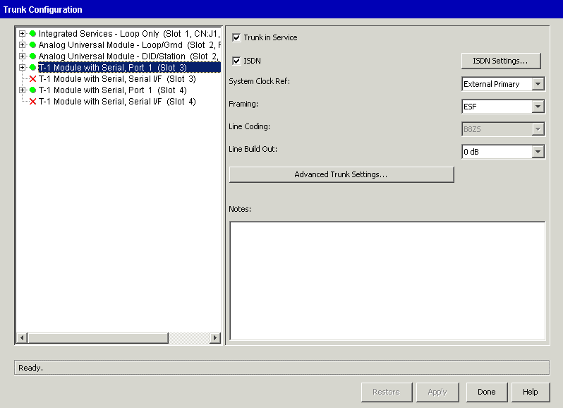
Note: If you want to configure a module for cross-connection to a serial interface, Be sure that you select the module labeled"Serial".
|
4
|
If the trunk is ISDN, check the ISDN check box, and click ISDN Settings to configure the ISDN trunk settings as follows: |
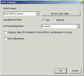
Note: If you do not select the ISDN check box, the trunk will be a CAS (Channel Associated Signaling) T-1 trunk, which implies robbed-bit signaling or clear channel for data. Clear channels (whether ISDN or CAS) must be assigned to data connections, and channels grouped for data connections must be contiguous. All other channel types, like B channels, must be assigned to voice trunk groups. If you configure ISDN to use a voice trunk group, you can configure that ISDN connection for dial-up data.
|
a
|
Select a variant in the Switch Variant drop-down list. |
Refer to your T-1 Service Confirmation Letter to determine which of the following ISDN switch variants to use:
Select the NT DMS-100 /S-100 variant when connecting to a Northern Telecom Meridian DMS-100 PBX configured with a subtype profile of S-100. In this scenario, the DMS-100 must be configured as the network side. Wave is always the user side.
|
b
|
Click Service Code Table to modify the service code table for the switch variant that you specified in the previous step. |
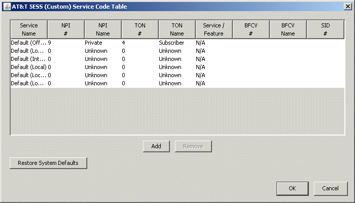
Note: You do not need to modify the service code table during initial configuration. The defaults should be sufficient for connecting to a local exchange carrier.
|
c
|
If your ISDN trunks support multiple services, click Add to add new service name records to the service code table, then modify the new records by clicking in each field to open a text field or a drop-down list. |
Note: The new entries in the service code table appear aISDN Setting options in the outbound routing tables. You will configure the outbound routing tables in Configuring outbound routing tables. You can select these settings on a call-by-call basis.
You can modify the following fields for new entries and existing entries:
|
•
|
Service Name. A text string, such as OUTWATS, FX, TIE, VNET |
|
•
|
NPI #. Numbering Plan Identifier, 0 through 15. |
|
•
|
0 = unknown, the network has no knowledge of the numbering plan so it uses the NANP. |
|
•
|
1 = ISDN/telephony number plan. Enter the name E.164 in the NPI Name field. |
|
•
|
9 = private numbering plan (private network). |
|
•
|
NPI Name. A text string describing the Numbering Plan Identifier; typically E.164, Unknown, or Private. |
|
•
|
TON #. Type of Number. There can only be four different types of entries: |
|
•
|
1 = international number. |
|
•
|
TON Name. A text string describing the Type of Number; typically National, International, or Unknown. |
|
•
|
Service/Feature. Service vs. Feature. Typically left N/A unless the provider states that it should be either Service or Feature. |
|
•
|
If you select Service or Feature, you need to configure the next three settings: |
BFCV #. Binary Facility Coding Value, 0 through 31.
A number for the service must be entered in the BFCV field. The provider provides this number. The number can be from 0 through 31.
Some common Service IDs:
|
•
|
1 = SDN (including GSDN) = in/out. |
|
•
|
2 = Toll free MEGACOM= in. |
|
•
|
6 = ACCUNET Switched Digital Service = in/out. |
|
•
|
7 = Long Distance Service = in/out. |
|
•
|
8 = International Toll Free Service = in. |
|
•
|
10 = ATT MultiQuest = in. |
|
•
|
17 = Call Redirection Service = in. |
BFCV Name. A text string describing the BFCV value.
SID #. Service Identifier, 0 through 127. Used primarily by Bell Canada.
If you are not sure of your changes, click Restore System Defaults to restore your changes to the system defaults.
|
d
|
Select the appropriate mode. |
|
•
|
User. This is the typical setting, unless you are connecting two Wave Servers together. |
|
•
|
Network. Use this setting if you are connecting two Wave Servers together. In this case, one Wave Server must be set to User and the other set to Network. |
Caution! These settings should not be adjusted unless you are instructed to do so by your Vertical Technical Support representative.
|
e
|
Select the Outgoing Caller ID Provided by Central Office check box if your contract specifies that the central office will provide Caller ID. |
In this case, the central office will typically provide the ISDN trunk’s billing number as Caller ID for all outgoing calls.
To configure ISDN channel settings, see Configuring digital channels for ISDN.
|
f
|
Check the Send Calling Name check box if you want Wave to send the name specified in the General Settings applet when calls are sent over this trunk. |
|
5
|
Specify the system clock reference in the System Clock Ref drop-down list. Available options are: |
|
•
|
Internal. The selected T-1 trunk will not be a clock reference source for the Wave Server, rather, the selected T-1 will act as a clock reference for the equipment connected to the T-1 trunk. This is useful if the Wave Server is to be master clock to another Wave Server or internal device. In this case, the other device should be configured as External. |
|
•
|
External Primary. The Wave Server gets its primary clock reference from the selected T-1 trunk. Use this for a T-1 trunk connecting to the PSTN. Only one trunk can be primary. |
|
•
|
External Secondary. If the primary T-1 trunk fails, the Wave Server will get its primary clock reference from the secondary T-1. Only one trunk can be secondary. |
Note: If you configure one trunk as secondary, the other trunk must be primary. If you have only one T-1 connection between your Wave Server and the PSTN, that connection must be the primary one. If you have two T-1s connected, the connection you are using for voice must be the primary one, and the other (typically set for data use) is secondary.
|
6
|
Set the following fields using the information on your T-1 Service Confirmation Letter. |
|
•
|
Framing. ESF (Extended Super Frame) or SF/D4 (Super Frame - D4). ISDN PRI is generally ESF. |
|
•
|
Line Coding. B8ZS (Bipolar 8 Zero Substitution) or AMI (Alternate Mark Inversion). ISDN PRI is B8ZS; AMI is not supported for ISDN. |
|
•
|
Line Build Out. 0 dB, -7.5 dB, -15 dB, and -22.5 dB are available if DSX mode is selected in Advanced Trunk Settings. Otherwise, in CSU mode, 0, -7.5, and -15 are available. |
|
7
|
Record information in the Notes field. This information could include circuit specific information or other information from the Trunk Configuration property sheet. Circuit number and carrier information or brief notes regarding issues encountered can be entered in this comment field. Field personnel can use this data to locate and identify the physical circuit connected to the Wave Server. |
|
9
|
Click Apply to save your changes. |
|
10
|
Click Done to return to the Management Console. |
Configuring dial-up routing
Configuring digital channels
Configuring digital channels for voice
Configuring digital channels for data
Configuring digital channels for ISDN
Assigning digital channels to a serial interface
Configuring outbound routing tables
Configuring digital channels
|
2
|
Display the card or module channels, and select the channels you want to configure. |
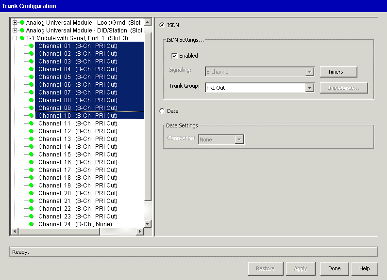
Note: If you checked the ISDN check box at the digital card or module level, you will see channel settings for ISDN and Data here at the channel level. If you did not check the ISDN check box, you will see channel settings for Voice and Data here.
|
3
|
Select Voice or Data. Note that if you selected ISDN previously, your choices are ISDN or Data. |
|
4
|
Configure the appropriate settings based on the channel type. |
Note: For ISDN channels, Channel 24 is automatically set to D-Ch, None.
|
5
|
Click Apply to save your changes. |
|
6
|
Click Done to return to the Management Console. |
Configuring dial-up routing
Configuring digital trunk card or module settings
Configuring digital channels for voice
Configuring digital channels for data
Configuring digital channels for ISDN
Assigning digital channels to a serial interface
Configuring digital channels for voice
|
1
|
Be sure that the channels are enabled—to do so, select the Enabled check box. |
|
2
|
Select the signaling method from the Signaling drop-down list. |
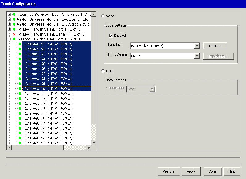
For T-1 voice channels,E&M Wink Start (FGP), E&M Immediate Start, or Ground Start are valid options.
If you have a fractional T-1 trunk, be sure all voice channels that are not in service on your trunk have the Enabled check box unchecked.
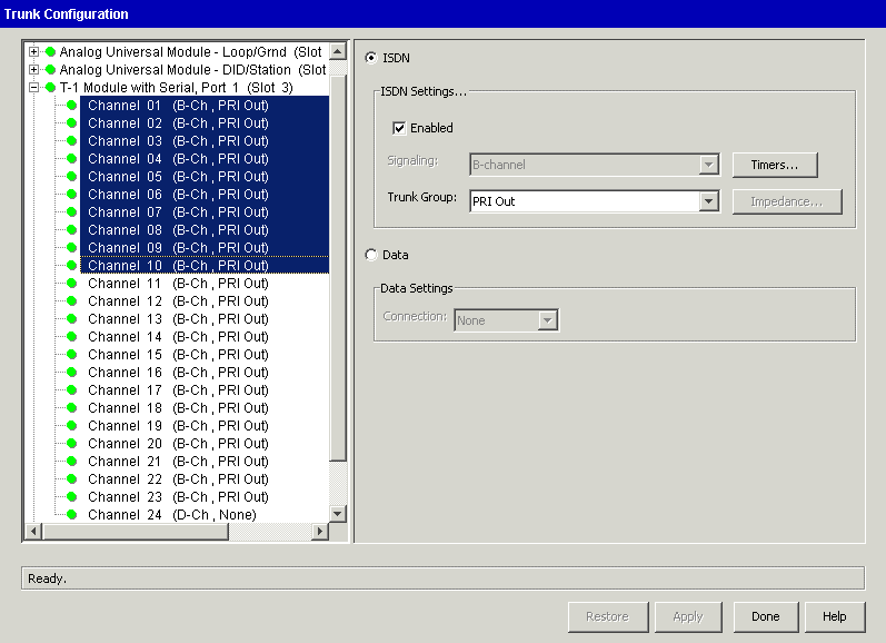
Note: If you chose the ISDN trunk type when you configured the T-1 module settings, Wave automatically sets the Signaling fields for channels 1 through 23 to B-channel; channel 24 is automatically set to D-channel.
|
3
|
To enable incoming Caller ID on ISDN trunks, click Timers. |
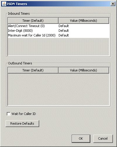
In the ISDN Timers dialog, select the Wait for Caller ID checkbox.
Warning! Do not change any of the other settings in the ISDN Timers dialog unless you are instructed to do so by your Vertical Technical Support representative in order to address a specific issue.
|
4
|
Click OK to close the ISDN Timers dialog. |
|
5
|
Specify the Trunk Group for the selected channels. |
One or more channels can be assigned to a particular voice trunk group. For example, if your trunk has 12 (1-12) 2-way voice channels, you can assign the Digital trunk group to channels 1 through 12.
Warning! If the trunk group you select is a Single Call variant outside line-enabled trunk group and you had previously selected more than one channel in step 2 of Configuring digital channels, you will see an error message similar to the following. Click OK to clear the message, and go back and select a single channel:

|
6
|
Click Apply to save your changes. |
|
7
|
Click Done to return to the Management Console. |
Configuring dial-up routing
Configuring digital channels
Configuring digital trunk card or module settings
Configuring digital channels for data
Configuring digital channels for ISDN
Assigning digital channels to a serial interface
About trunk groups
Trunk groups
Configuring digital channels for data
|
1
|
Specify the Connection for the selected channels from the drop-down list. |
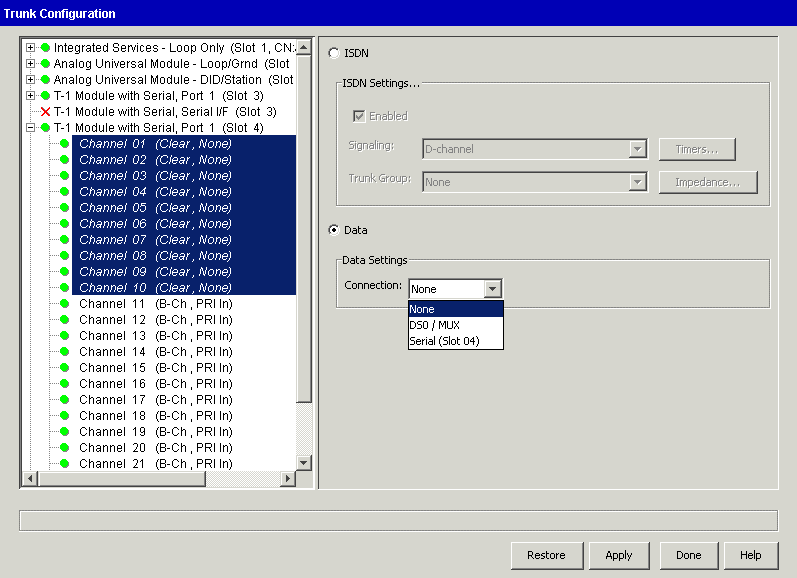
One or more channels can be assigned to a particular data connection. For example, if your trunk has 12 (13-24) data channels, you can assign the DS0/Mux connection to channels 13 through 24.
Note: Channels assigned to the same digital connection or DS0/Mux trunk group must be contiguous.
You can select from the following connections to transport data between the Wave Server and the WAN:
If you are configuring your T-1 trunk to be a T-1/DS0 multiplexor, choose the T-1 DS0/Mux connection for the channels you want to multiplex. You must also assign the same number of channels to the T-1 DS0/Mux on the other T-1 port.
Note: When a channel is set to the T-1 DS0/Mux, the trunk is automatically enabled.
|
2
|
Click Apply to save your changes. |
|
3
|
Click Done to return to the Management Console. |
Configuring dial-up routing
Configuring digital channels
Configuring digital trunk card or module settings
Configuring digital channels for voice
Configuring digital channels for ISDN
Assigning digital channels to a serial interface
Configuring digital channels for ISDN
Note: For information about configuring an ISDN data connection for dial-up, see Configuring dial-up routing. The information in this section also applies to ISDN PRI.
|
1
|
Ensure that the Enabled check box is selected. |
|
2
|
Select a Trunk Group from the drop-down list. |
|
3
|
Click Apply to save your changes. |
|
4
|
Click Done to return to the Management Console. |
Configuring dial-up routing
Configuring digital channels
Configuring digital trunk card or module settings
Configuring digital channels for voice
Configuring digital channels for data
Assigning digital channels to a serial interface
Assigning digital channels to a serial interface
|
1
|
If necessary, click the Administration tab of the Management Console. |
|
2
|
Click Trunk Configuration, located in the Trunk Administration section. |
|
3
|
Select the Data option. |
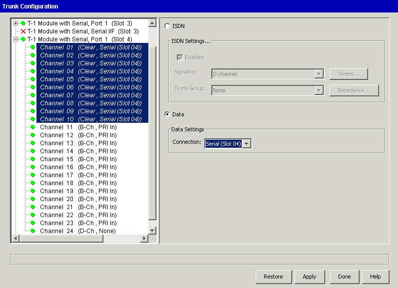
Hint: Unlike other data channels, you can select and configure non-contiguous channels for the serial interface.
|
4
|
Select the Serial connection to use from the Connection drop-down list. |
|
5
|
Click Apply to save your changes. |
|
6
|
Click Done to return to the Management Console. |
Typically, assigning channels to the serial connection is all you need to do. You might want to ensure that your serial interface’s configuration is correct, or make some changes to it, if your connection is not working.
For more information, see Ensuring that the T-1 serial interface is set correctly.
Configuring ports and channels on the Quad BRI Module
The Quad BRI Module supports ISDN Basic Rate Interface (BRI) digital trunks. The Quad BRI Module provides connectivity between the Wave Server and Central Office (CO) equipment supporting Euro-ISDN BRI communication protocols.
The Quad BRI Module supports 4 Euro-ISDN BRI trunks and up to 8 simultaneous voice calls.
Note: The following procedures call out information specific to configuring ports and channels on the Quad BRI Module. For more about general trunk and channel configuration settings not described in detail here, see Configuring digital trunks and channels. Also, refer to your Service Confirmation Letter or contract to determine specific settings to use.
To configure ports on the Quad BRI Module
|
1
|
If necessary, click the Administration tab of the Management Console. |
|
2
|
Click Trunk Configuration, located in the Trunk Administration section. |
|
3
|
In the Trunk Configuration applet, select the port, and then select the Trunk in Service checkbox. |

Note: The ISDN checkbox is always selected for each port on the Quad BRI module, and cannot be changed. Also, the Advanced Settings button is disabled.
|
4
|
Click the ISDN settings button. The ISDN Settings dialog opens. |
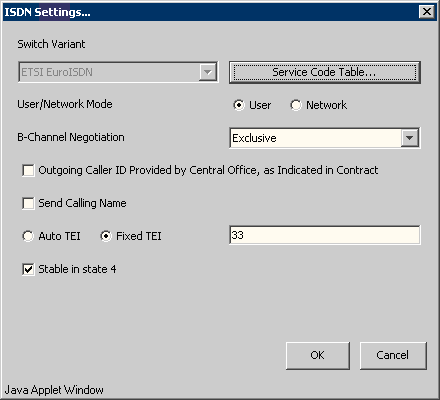
Note: The Switch Variant ‘ETSI EuroISDN’ is automatically selected and cannot be changed. You do not need to modify the Service Code Table during initial configuration—the defaults should be sufficient for connecting to a local exchange carrier.
|
5
|
Enter the following information: |
|
•
|
User/Network Mode. Select one of the following: |
|
•
|
Select User (the default) if you are configuring this port or ports to communicate over an external BRI trunk to the CO. |
|
•
|
Select Network if you are configuring this port or ports to communicate over an internal BRI trunk to an ISDN device such as a fax machine, modem, and so forth. |
|
•
|
B Channel Negotiation. Select Exclusive or Preferred from the drop-down list. |
|
•
|
Send Calling Name. Select this checkbox if you want Wave to send the name specified in the General Settings applet when calls are sent over this trunk. |
|
•
|
Specify the TEI (Terminal Endpoint Identifier) to use. TEI is a code supplied by an ISDN device and is used by the service provider switch to identify the calling device. Select one of the following: |
|
•
|
Auto TEI. Auto TEI is obtained from the network via a message protocol, and is typically used for point-to-multipoint configurations. |
|
•
|
Fixed TEI. Enter a value between 0-63 inclusive in the text box. Typically, a TEI value of 0 is used in a point to point configuration. |
|
•
|
Stable in state 4. This option is not supported in this version. |
|
6
|
Click OK to save your changes. |
|
7
|
Repeat these steps for the other ports on the Quad BRI module. |
To configure channels on the Quad BRI Module
|
1
|
In the Trunk Configuration applet, select the channel or channels on the Quad BRI Module that you want to configure, and then select the Enabled checkbox. |
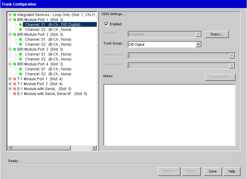
Note: The Signaling setting defaults to B-channel and cannot be changed. The Transmit Gain and Receive Gain settings do not apply to the Quad BRI Module and are disabled, as well as the Impedance button.
|
2
|
Select the Trunk Group for the selected channels from the drop-down list. |
|
3
|
Enter any additional Notes for reference. |
|
4
|
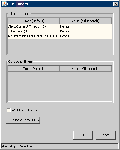
To enable incoming Caller ID on BRI trunks, click the Timers button. The ISDN Timers dialog opens. |
|
5
|
Select the Wait for Caller ID checkbox. |
Note: Do not change any of the other settings in the ISDN Timers dialog unless you are instructed to do so by your Vertical Technical Support representative in order to address a specific issue.
|
6
|
Click OK to save your changes. |
|
7
|
Repeat these steps for the other ports on the Quad BRI module. |
Ensuring that the T-1 serial interface is set correctly
Configuring digital channels
Configuring dial-up routing
Configuring digital trunk card or module settings
Configuring digital channels for voice
Configuring digital channels for data
Configuring digital channels for ISDN
Enabling trunks for external pager and call notifications
For any trunks that will be used for external pager or call notifications, you must make the following configuration changes in order for these features to work. This information applies to all trunk types.
Note: For information on how to set up notifications for a user, see The Voice Mail \ E-mail, Pager, and Call Notification tabs .
To enable trunks for external pager and call notifications
|
1
|
If necessary, click the Administration tab of the Management Console. |
|
2
|
Click Outbound Routing, located in the Trunk Administration section. |
|
3
|
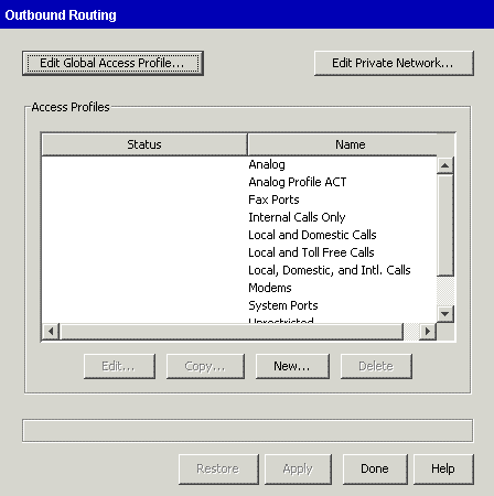
The Outbound Routing dialog opens. |
|
4
|
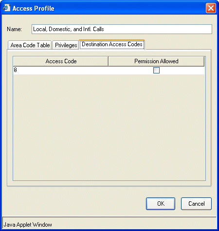
Select the System Ports access profile and click Edit. When the Access Profile dialog box opens, click the Destination Access codes tab. |
|
5
|
Select the Permission Allowed checkbox for all access codes that are being used for external pager and call notifications. In the example above, “8” was set up previously as a trunk access code in the First Digit Table. (See About the First Digit Table.) |
|
6
|
Click OK, and then click Done. |


