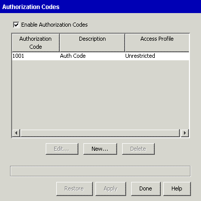
Configuring authorization codes
Use the Authorization Codes applet to configure numeric passwords that allow users to place calls on phones and phone lines where call access is restricted.
Authorization codes can be used on analog, digital, and SIP phones. On digital phones, authorization codes can be used on both primary and secondary line appearances and outside lines. Refer to the Wave Phone User Guide for information about using authorization codes.
To add authorization codes
| 1 | If necessary, click the Administration tab of the Management Console. |
| 2 | Click the Authorization Codes icon, located in the PBX Administration section. |
The Authorization Codes applet starts.

| 3 | Click New to open the Authorization Code dialog. |
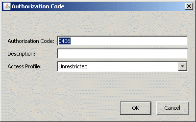
The Authorization Code field is automatically populated with a randomly selected unused 5-digit number. You may change this number to any 3- to 12-digit number.
You can use x's as wildcard characters when entering an authorization code, using any combination of leading, trailing, or embedded wildcard characters. When a user enters an authorization code, any key that he or she presses in the wildcard position will be accepted. If you use multiple wildcard characters, the user must enter the same number of digits for the authorization code to be accepted. For example, if you define the authorization code "0xx6", "0406" will be successful, but "046" will fail.
| 4 | Enter a Description. |
| 5 | Choose an Access Profile from the drop-down list. |
The Access Profile determines what types of calls can be made on a Wave extension using this authorization code. The default is Unrestricted access.
| 6 | Click OK to add the Authorization Code to the list. |
| 7 | Check the Enable Authorization Codes check box. |
Authorization codes cannot be used until the Enable Authorization Codes check box is checked. When you are ready to enable authorization codes, check the Enable Authorization Codes check box.
| 8 | Click Apply to save your changes. |
| 9 | Click Done to return to the Management Console. |
The Call Park feature places a call on an extension or in a system parking slot for retrieval from another phone.
| 1 | In the General Settings applet, click the PBX Advanced tab. |
| 2 | In the Call Park group box, specify the following call park settings: |

| • | Hold ___ seconds before ring back. Select the number of seconds that Wave waits for a user to pick up a held call. If the call is not picked up within the specified time, Wave rings the extension from which the call was held. |
If you specify unlimited seconds, Wave does not ring back the extension.
| • | System park ___ seconds before ring back. Select the number of seconds that Wave waits for a user to pick up a parked call. If the call is not picked up within the specified time, Wave rings the extension from which the call was parked. |
If you specify unlimited seconds, Wave does not ring back the parking extension.
| • | Self/Directed park ___ seconds before ring back. Select the number of seconds that Wave waits for a user to pick up a self-parked (or directed-parked) call. If the call is not picked up within the specified time, Wave rings the extension from which the call was parked. |
If you specify unlimited seconds, Wave does not ring back the extension.
| • | Require manual line selection to answer ring back for held/parked call. This checkbox controls what happens when you pick up the handset of a phone that has a call on hold or a parked call on the primary line: |
| • | If checked, the phone provides dial tone when you pick up. To connect to the held/parked call, you must select its line manually. |
| • | If unchecked, picking up the phone connects you to the held/parked call on the primary line. |
Configuring call pickup groups
You can configure call pickup groups—groups of extensions that can be answered by all the users in the group using the Group Pickup phone feature—and add extensions to them in the User/Group Management applet.
There are two methods to pick up a call in a pickup group:
| • | Group. Any group member can answer the ringing extension of any other group member. Members in this group can press the Group Pickup button on a digital phone or some SIP phone models, or dial *74 to answer a call. |
Note: An extension can belong to only one pickup group.
To create a pickup group
| 1 | If necessary, click the Administration tab of the Management Console. |
| 2 | Click the User/Group Management icon, located in the PBX Administration section of the Management Console. |
| 3 | Log on to the User/Group Management applet, which opens in a remote access window. Once you log on, the Users view opens. |
| 4 | Choose File > New > Pickup Group. The Pickup Group dialog opens. |
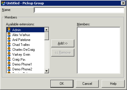
| 5 | Enter a Name for the Pickup Group. |
| 6 | Select the users you want and move them into the Members list by clicking Add. Hold down the CTRL key as you click to select multiple users. When assigning extensions to pickup groups, remember that an extension can belong to only one pickup group. |
| 7 | Click OK. The Pickup Groups that you have defined appear in the Pickup Groups view. Click its icon in the view bar of the User/Group Management applet to see and manage Pickup Groups. |
Caller ID refers to the phone number and name that identify a caller. There are three types of Caller ID that you can configure in Wave:
| • | External Caller ID refers to the name and number that identifies the caller when a call is sent by Wave over an ISDN-PRI trunk to the central office. |
| • | Internal Caller ID refers to the name and number that identifies the caller on a station-to-station call that originates on the Wave Server or a PBX connected to the Wave Server. |
| • | Inbound Caller ID refers to the name and number that identifies the caller on a call received from an inbound call from an inbound trunk group, IP telephony source, or outside line. |
Configuring external Caller ID
External Caller ID refers to the name and number that identifies the caller when a call is sent by Wave over an ISDN-PRI trunk to the central office. External Caller ID can only be sent on an ISDN-PRI trunk. (Wave does not send Caller ID on analog trunks. If Caller ID is enabled on T-1 wink start or ground start trunks, the central office must be capable of receiving ANI/DNIS format.)
In order to send a name with the Caller ID information, the call must be placed on an ISDN trunk, the Send Caller Name option must be selected in the trunk configuration, and the far end has to accept the name.
When an internal extension initiates a call, its external Caller ID is determined by the settings configured in the General Settings and the User dialog, User \ External Caller ID tab. When a trunk initiates an outbound call (a tandem call) the external Caller ID is the same as the received Caller ID (or it is the trunk group name if no Caller ID is received).
By default, Wave sends no Caller ID to the trunks. Outbound trunk groups and IP telephony call destinations are the gatekeepers of external Caller ID. At this level Wave decides whether to send external Caller ID to the trunk and in what format.
To send Caller ID with outbound calls, you must perform the following tasks
| • | Configure trunk-specific Caller ID settings. |
| • | Configure the system-wide Caller ID settings. |
By default, all internal extensions send the external Caller ID specified in the General Settings applet. For users with specific Caller ID requirements, configure the Caller ID settings in the User dialog to override the General Settings Caller ID format (see Configuring user-specific Caller ID settings).
Hierarchy of external Caller ID settings
External Caller ID can be applied at three different levels: system-wide, user-specific, and trunk-specific.
| • | System-wide external Caller ID is specified via the General Settings applet, PBX tab. |
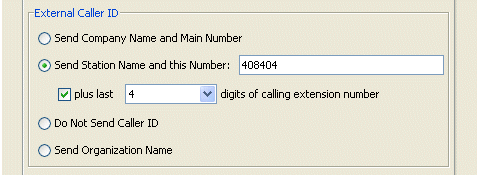
By default, system-wide external Caller ID is not sent.
| • | User-specific external Caller ID setting, if specified, overrides the system-wide setting. The user-specific external Caller ID setting is set for the user via the User/Group Management applet, User dialog \ External Caller ID tab. |
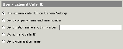
By default, external Caller ID at the user-specific level uses the system-wide setting.
| • | Trunk-specific external Caller ID setting, if specified, overrides the user-specific setting. By default, trunk-specific external Caller ID is not sent. |
Trunk-specific external Caller ID can be set in two places:
| • | For outbound analog or digital trunks, external Caller ID is set via the Trunk Groups applet, Out tab. |
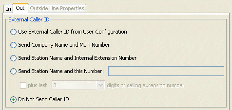
| • | For an outbound IP call destination, external Caller ID is set via the IP Telephony applet. (Click Call Routing > Signaling Control Points, edit the SCP, and then click the Outbound Routing tab.) |
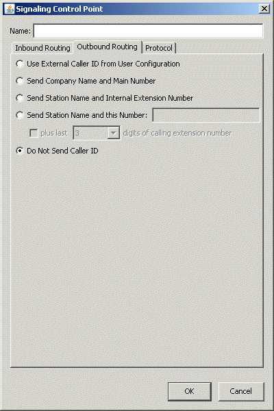
For example, if at the system-wide level you choose to use the Company Name and Main Number, and at the user-specific level you choose to send no Caller ID, Caller ID will not be sent by calls made from that extension. However, if at the trunk-specific level you choose to send the Company Name and Main Number, then the Company Name and the Company Main Number are sent even though the user-specific Caller ID settings specified otherwise.
Configuring internal Caller ID
Internal Caller ID refers to the name and number that identifies the caller on a station-to-station call that originates on the Wave Server or a PBX connected to the Wave Server. You do not need to configure internal Caller ID for extensions—it is always the Display Name and the extension number as specified in the User dialog.
Inbound Caller ID refers to the name and number that identifies the caller on an inbound call received from an inbound trunk group, IP telephony source, or outside line. When a call arrives from a trunk (or IP telephony source), Wave may or may not receive Caller ID.
| • | If the Wave does receive Caller ID, this information is sent along with the call to its destination, whether it be internal or external. |
| • | If Caller ID is not received, Wave assigns Caller ID information to the call depending on the call source: |
| • | Inbound Trunk Group. If the name is missing, the trunk group name (Digital, for example) is sent. If the number is missing, no number is sent. |
| • | IP Telephony. If the name is missing, “IP Telephony” is sent. No number is sent with an IP telephony call. |
Configuring trunk-specific Caller ID settings
The trunk-specific Caller ID format determines whether Caller ID will be sent to the trunk and in what format. In the Trunk Groups and IP Telephony applets, you can configure the Caller ID values as they are supported by the trunks associated with the outbound trunk group or IP call destination. Configuring Caller ID on a particular outbound trunk group affects all the trunks and digital channels associated with the trunk group.
Caution! Check your Service Confirmation Letter to determine whether Caller ID is supported on your trunks and in what format. Sending Caller ID to a trunk that does not support it might cause your calls to fail.
To configure trunk-specific Caller ID settings
| 1 | Specify the appropriate Caller ID settings for your application. |
| • | To specify Caller ID settings for an outbound trunk group. In the Trunk Groups applet, edit the trunk group, and select the Out tab. |
| • | To specify Caller ID settings for an IP call destination. In the IP Telephony applet,expand Call Routing > Signaling Control Points. Edit the call destination and click the Outbound Routing tab. |
| 2 | Select an external Caller ID setting: |
| • | Use External Caller ID from User Configuration. For calls initiated from stations, sends external Caller ID as specified in the User dialog. |
| • | Send Company Name and Main Number. Sends the Company Name and Company Main Number. |
| • | Send Station Name and Internal Extension Number. For calls initiated from stations, sends the Display Name and extension number set in the User dialog. |
Use this setting for trunks connected to other PBXs.
| • | Send Station Name and this Number. For calls initiated from stations, sends the call source Display Name and the specified Number. |
Use this setting to provide the station name and phone number on outbound calls.
Optionally, select the plus last check box to append the specified number of digits of calling extension number to the digits specified in the Number field.
If the plus last check box is selected, the specified number of digits of calling extension number are appended to the digits specified in the Number field.
Use this setting to provide the station name and phone number on outbound calls.
Note: If this setting is your choice, it is generally recommended that you set this at the system-wide level in the General Settings applet.
| • | Do Not Send Caller ID. Sends no external Caller ID from this trunk group or IP call destination. |
Use this setting for trunks that do not support Caller ID, or for trunks where you want to block external Caller ID.
Configuring system-wide Caller ID settings
Configure the system-wide Caller ID settings for calls initiated by internal extensions in the General Settings applet. Remember that the external Caller ID is only sent to the central office if the trunk group is configured to send external Caller ID.
To configure system-wide Caller ID settings
| 1 | In the General Settings applet on the System tab, if you have not already done so enter the Company Name and Company Main Number. |
Note: While Company Name can include up to 16 alphanumeric characters, Caller ID cannot send more than 15 characters over ISDN.

On the PBX tab, select a default External Caller ID setting for calls initiated by stations. Select one of the following options:
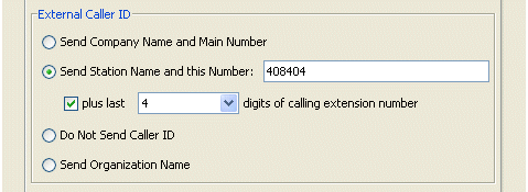
| • | Send Company Name and Main Number. Sends the Company Name and Company Main Number as external Caller ID. |
Use this setting to provide some Caller ID information while keeping the actual calling extension number private.
| • | Send Station Name and this Number. Sends the Station Name (specified via the User/Group Management applet) followed by the digits entered in the adjacent field. |
If the check box is selected, the specified number of digits from the calling extension number are appended to the digits specified in the field.
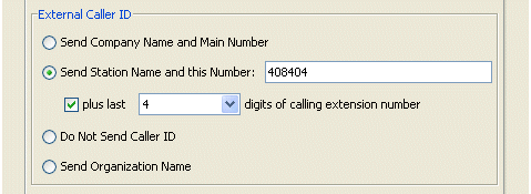
For example, if you enter 4085227, and specify that the last 3 digits be added to the number, a call from extension 1234 will send the number 408-522-7234.
Use this setting to provide the station name and phone number on outbound calls.
| • | Do Not Send Caller ID. Wave will not provide external Caller ID. |
| • | Send Organization Name. This option is not supported in this version. Sends the name of the Organization to which the calling user belongs. For more about Organizations, see Using OrganizationsUsing Organizations. |
Configuring user-specific Caller ID settings
By default all users send the external Caller ID format specified in the General Settings applet. To override the system-wide Caller ID settings for a specific user, see .
Configure the settings that determine how long Wave should wait after you finish dialing before placing the call.

In the General Setting applet (PBX (Advanced) tab, Dialing section), set When dialing, wait up to ___ seconds for next digit to be entered. This drop-down list sets the dialing timeout. If the specified time elapses before another digit is pressed, Wave will stop collecting digits and attempt to route the call based on the digits collected.
The dialing timeout is useful for dialing numbers of a length not expected by your dialing plan. For example, in North America, numbers are generally 7, 10, or 11 digits in length. If you are dialing an international number the length of the number will be longer than expected, or if you are dialing the local operator the number will be shorter. After you have finished dialing the number, Wave will wait the number of seconds specified in the drop-down list, and place the call as dialed.
Requiring an access code for emergency number dialing
By default, Wave allows users to dial emergency numbers directly.
To help prevent accidental emergency calls, you can require users to dial an external access code before dialing an emergency number. This setting is disabled by default since users may expect to simply dial the emergency number (for example “911” in North America or "112" in EU countries) to access emergency services.
Important! If you require an external access code to dial an emergency number, be sure that all users know about this requirement, and that they know the access code to use.
To require an external access code for emergency number dialing
| 1 | In the General Settings applet, click the PBX (Advanced) tab. |
| 2 | Select the Require external access code to dial emergency numbers check box to enable this option. Deselect this checkbox if you want users to be able to dial an emergency number directly. |

You use the Outbound Routing applet to set up one or more emergency numbers. For details, see Setting up emergency dialing.
Configuring external call routing restrictions
Any time a call comes in to the Wave Server and is routed back out on another trunk (trunk-to-trunk), you must consider these external call routing restriction options. In this scenario a call is physically connected across two external trunks through the Wave Server.
Scenarios include off-site call forwarding, off-site transferring, and conferencing where two or more parties is an external phone number. These options can also affect your inbound call routing wherever you have an inbound call routed to an external destination.

You can configure the following options in the General Setting applet, PBX (Advanced)tab, in the Trunking group box:
| • | Off-Site Call Forward Password Required. Select this check box to require users to enter their voicemail passwords after specifying the external number when they forward their calls to an external phone number. (This option does not apply if a user is forwarding their phone to a Private Networking destination.) |
Users without passwords can enter the password 111 when prompted to forward calls to an external number.
Note: It is strongly suggested that you configure passwords for all users. Password security is crucial in preventing your company from being victimized by toll fraud, where unauthorized users gain privileged access to your telephone system and place outbound long distance or international calls that are then charged to you. In most cases, access is gained through unsecure, easy-to-guess passwords. By making your passwords more secure, you can dramatically increase the security of your Wave system against toll fraud. For more information, see Protecting Your Phone System Against Toll Fraud.
| • | Allow Analog Loop-Start Trunk-to-Trunk Connections. Select this check box to permit direct calls between analog loop-start trunks. Many connections of this type are left open, even after both parties hang up. If you select this check box, you can specify a maximum connect time in the Trunk-to-Trunk Maximum Connect Time field to ensure that the connection is closed after a specified amount of time. |
| • | Trunk-to-Trunk Maximum Connect Time (Minutes). This setting causes Wave to disconnect any trunk-to-trunk calls after the specified time limit. Setting this option helps avoid a situation where a trunk-to-trunk call is in a loop (for instance, both sides are busy) where neither side knows to terminate the call. Select Unlimited to prevent Wave from automatically terminating a trunk-to-trunk call. |
The Fax Redirect feature allows you to automatically redirect incoming fax calls to the extension that has a fax machine. Without Fax Redirect, fax calls to an extension without a fax machine would not be received.
You can configure a fax redirect extension for the system, and you can override it for any auto attendant.
To configure Fax Redirect for the system
| 1 | If necessary, click the Administration tab of the Management Console. |
| 2 | Click General Settings, located in the General Administration section. |
| 3 | Click the PBX tab. |

| 4 | Under Fax Redirect Service, select the extension where faxes can be received from the Redirect fax calls to drop-down list. |
Setting Fax Redirect for an auto attendant
For information on overriding the system fax redirect extension for calls to a particular auto attendant, see Creating a new auto attendant.
The system-wide music on hold source identifies the music that all callers on hold hear unless a user, auto attendant, or queue is configured to use a different source (see Customizing music on hold.)
This topic describes the following:
| • | Configuring a system port for music on hold. This step is required before you can select a specific WAV file to play to callers on hold, either (one of the options described later in this topic). |
| • | Enabling system-wide music on hold. |
To configure a system port for music on hold
| 1 | If necessary, click the Administration tab of the Management Console. |
| 2 | Click the Resource Management icon, located in the PBX Administration section |
| 3 | Expand the Application Resources folder. |
| 4 | Expand the Music On Hold folder, and then select Wave Player. |
| 5 | Select a port from the Wave Player drop-down list. |
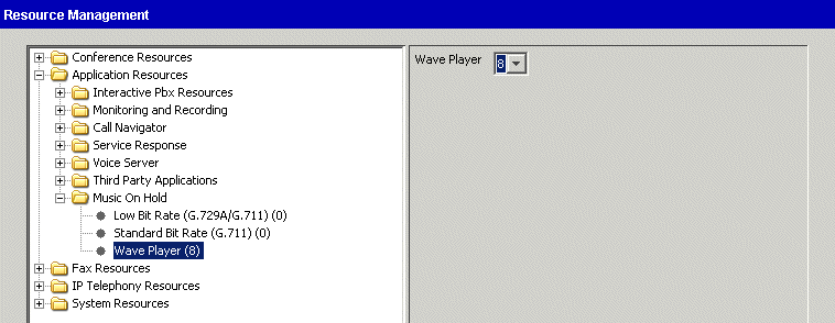
| 6 | Click Apply to save your changes, and click Done to close the Resource Management applet. |
To enable system-wide music on hold
| 1 | If necessary, click the Administration tab of the Management Console. |
| 2 | Click the General Settings icon, located in the General Administration section. |
| 3 | Select the PBX tab. In the Music On Hold section, specify the music-on-hold source to use as the System Default from the drop-down list: |
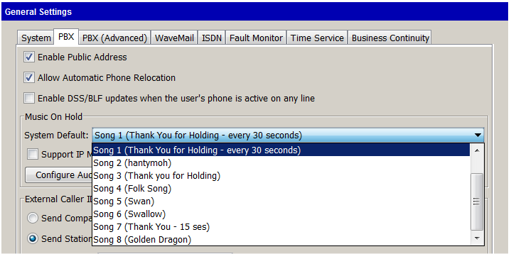
Select one of the following options:
| • | Disabled. No default music-on-hold source is specified. This setting does not affect a music-on-hold source specified for an individual user, auto attendant or Contact Center queue. |
Hint: It is highly recommended that you specify a default music-on-hold source so that a caller who reaches a user, auto attendant, or queue with no music-on-hold source specified does not hear extended ringing or silence, which may result in a hang-up.
| • | External (Audio Input Jack). Hold music is played from an external device, typically a CD player, radio, or specialized music-on-hold device. For more about using external music-on-hold devices with Wave, see “Music-on-hold systems” in Appendix B in the Wave Server Hardware Reference Guide. |
Note: Wave plays whatever is on the specified channel and does not monitor the channel. If the music device stops, callers on hold hear nothing.
| • | Song n (<song title>). Select the WAV file to play to callers on hold. You cannot select a specific WAV file here until you configure a system port for music on hold (described above). You identify the WAV files that are listed here via the Configure Audio Sources dialog, described in step 5. |
| 4 | To play hold music to calls on SIP phones or SIP trunks, select the Support IP Music On Hold checkbox. |
Important! If you see the following message, you need to exit the General Settings applet, allocate additional Music on Hold resources (either Low Bit Rate (G.729A/G.711) or Standard Bit Rate (G.711) resources) via the Resource Management applet, and then restart the General Settings applet.
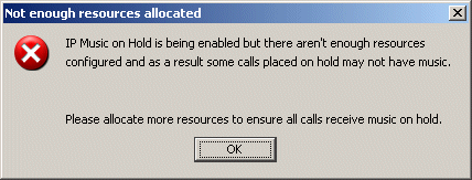
| 5 | Click Configure Audio Sources to open the Music On Hold Audio Sources dialog:. |
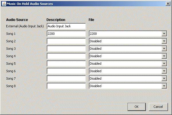
You use this dialog to identify the external and internal audio sources displayed in the System Default drop-down list (described above), and also in the music on hold source drop-down lists available when you edit a user, user template, auto attendant, or Contact Center queue.
| • | External (Audio Input Jack). Enter a descriptive label for the external music on hold device if you are using one, for example “FM Top 40 radio”. |
| • | Song 1 - Song 8. You can make up to 8 WAV files available for use in various music-on-hold scenarios. For each entry: |
| • | Select the song title or filename from the File drop-down list. |
| • | Enter a Description that will help users understand how various WAV files can be used, for example “After-hours main MOH”. If you do not enter a Description, the File name is used. |
To take a song out of use, select Disabled from the drop-down list. If you disable a song the following warning message is displayed, indicating that some users’ music-on-hold settings may be reset.
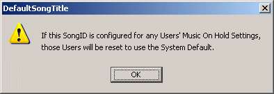
For more about creating and placing custom audio files for hold music, see Customizing music on hold.
| 6 | Click Apply or Done to save your changes. Your music on hold settings take effect immediately. However, calls currently on hold without music will remain without music. If you switch from a WAV file to an External hold music source, SIP calls currently on hold will continue to hear the WAV file. |
Each user, auto attendant, and Contact Center queue can have individualized hold music that is different from the default system hold music. See the following:
| • | User. See Setting the user’s hold music. |
| • | User template. See |
| • | Auto attendant. See |
| • | Contact Center queue. See “Setting up hold music” in Chapter 2 in the Wave Contact Center Administrator Guide. |
Important! You can select a specific WAV file to play to callers on hold in any of these scenarios. Before you can do so, you must first set up a system port for music on hold, as described in Configuring Music On Hold.
Using custom audio files for system hold music
You can use your own audio files for system hold music. To do so, you must convert each audio file to the format required by Wave, and then place the files in the correct location on the Wave Server. Custom audio files must be in 8-bit mu-law 8000 Hz mono WAV format—system hold music will not play back if you use a different file format.
To create audio files for music on hold
| 1 | Start with a audio file (WAV, MP3, and so forth) of your choice. |
| 2 | Launch an audio conversion tool. A recommended one is SmartSoft’s Smart WAV converter, available at http://www.smartwavconverter.com. (You will need the pro version.) |
| 3 | Convert your audio file to 8-bit mu-law 8000 Hz mono WAV file format and save it. |
To place the music on hold audio files in the correct locations
| 1 | Copy the converted WAV file to the following location on the Wave Server: |
C:\Inetpub\ftproot\Private\Options\Music
| 2 | If you have SIP phone users or IP trunks, copy the converted WAV file to the following location: |
C:\Inetpub\ftproot\Private\Options\IpMOHMusic
The Public Address feature requires third-party hardware for amplification on an analog-only Wave system. If you have digital phones, the speakers on the phones act as a public address system and announcements are sent to digital phone speakers as well as the overhead public address system.
To enable the public address system
| 1 | If necessary, click the Administration tab of the Management Console. |
| 2 | Click the General Settings icon, located in the General Administration section. |
| 3 | Select the PBX tab. |
| 4 | Select the Enable Public Address check box. |

Once Public Address is enabled, users can make announcements over the public address system and digital phone speakers by pressing the System Page button on digital phones, or dialing *11.
Enabling automatic phone relocation
When automatic phone relocation is enabled on the Wave Server, a previously-working digital phone will be recognized after it has been unplugged and moved to a new location, for example if a user switches offices. You do not need to manually reassign the phone’s extension or reprogram feature buttons after a move.
Automatic phone relocation supports two methods of phone relocation, depending on the digital phone type:
| • | Auto recognition is supported only on Comdial digital phones (Edge100, 700, 80xx, and 83xx). |
Comdial digital phones store the extension assigned when the phone last came into service. When a previously-working Comdial digital phone is plugged in at the new location, the user is asked if he or she wishes to retain the extension assigned to the phone.
| • | If the user responds YES, all phone-specific information—programmed feature buttons, speed dial numbers, and so forth—is retained at the new location. |
| • | If the user responds NO (or if the user lets the question time out after about 2 minutes), *98 must be used for automatic phone relocation, as described below. |
| • | Relocation Feature Code *98 is supported on all digital phones, including those listed above. Dialing *98 + an extension on a digital phone assigns that extension to the phone. The extension to be assigned cannot currently be in service. |
A user can use *98 to either physically move his or her digital phone to a new location, or to swap a phone with another user. For example, Joe (x201) is moving into Frank's (x205) old office. They both have the same digital phone model. Joe unplugs his phone (so x201 is no longer in service) and leaves it in his old office. He then goes to his new office and dials *98 201 on Frank’s old phone. Frank's phone is configured with Joe's extension with all of Joe's feature buttons, call history, and other phone information automatically relocated from his old phone.
The phone must be operable before the user can dial *98 from it. This means that one of the following must be true:
| • | The new slot and port where the phone is relocated to must already be preprogrammed as a similar phone model (via the slot/port and Telephone type fields on the User tab of the User dialog). |
In this case, the phone will come into service as the extension of whichever user is programmed at that slot/port, and then *98 can be dialed to reassign the new extension to this slot/port. The slot/port of the user that was previously programmed at that location will be cleared, but the user itself will not be deleted.
| • | There must be one or more users (extensions) defined in the Wave database with a similar Telephone type but with no slot/port assigned. |
In this case, when a phone is plugged into a slot/port that is not associated with any extension and available unassigned extensions exist in the database, the Auto Configuration feature is invoked and “BEGIN” is displayed on the phone’s LED screen to allow an available extension to be selected. Once an available extension is selected the phone will come into service as that extension. Then *98 can be dialed to assign the relocating user’s extension to this phone. Note that the relocating user’s extension is not offered during Auto Configuration because in the Wave database it is still associated with the slot/port at its old location.
If neither of these configuration scenarios is true, the phone’s LED display will show the slot and port the phone is plugged into, and a status of “Unassigned”. Until you resolve one of the scenarios, the phone will never come into service and you will not be able to use *98.
To configure automatic phone relocation
| 1 | If necessary, click the Administration tab of the Management Console. |
| 2 | Click the General Settings icon, located in the General Administration section. |
| 3 | In the PBX tab of the General Settings applet, select the Allow Automatic Phone Relocation check box. |

| 4 | Click Apply to save your changes. |
| 5 | Click Done to return to the Management Console. |
Enabling DSS/BLF updates when the user’s phone is active on any line
A Direct Station Select/Busy Lamp Field (DSS/BLF) feature button on a digital phone monitors the state of a specific extension, and provides a quick way for a user to place or transfer a call to that extension. A DSS/BLF feature button can be in one of the following states:
| • | A solid red LED next to a DSS/BLF button indicates that the extension is in use. |
| • | A flickering red LED indicates the extension is ringing. |
| • | A blinking LED indicates that the extension has a call on hold, or the extension is in Do Not Disturb mode. |
By default, the DSS/BLF feature button only reflects the state of the assigned extension's primary line. When you perform the steps described below, a DSS/BLF feature button on a user’s digital phone will reflect the assigned extension’s state for any line, not just the extension’s primary line. For example, if the user at extension 201 is busy on an Outside Line or on a line appearance, another user with a DSS/BLF feature button assigned to extension 201 will see that the user is busy on a call.
To enable DSS/BLF updates when a user’s phone is active on any line
| 1 | If necessary, click the Administration tab of the Management Console. |
| 2 | Click the General Settings icon, located in the General Administration section. |
| 3 | In the PBX tab of the General Settings applet, select the Enable DSS/BLF updates when the user’s phone is active on any line check box. |

| 4 | Click Apply to save your changes. |
| 5 | Click Done to return to the Management Console. |
Note: This option is enabled or disabled on a global basis for all users.
Enabling call return for external calls
This option allows a user to automatically call back the last inbound external call via the *69 phone command or a phone feature button configured for Call Return. If this option is not enabled, users cannot automatically call back external calls. The Trunk Access Code (TAC) that you specify according to the following steps is prepended to the phone number of most recent inbound external call before the call is returned.
To enable call return for external calls
| 1 | If necessary, click the Administration tab of the Management Console. |
| 2 | Click the General Settings icon, located in the General Administration section. |
| 3 | In the PBX (Advanced) tab of the General Settings applet, in the Dialing section select the Enable Call Return ___ Trunk Access Code (TAC) check box. |

| 4 | Enter the trunk or external access code required to make an external call, typically 9. |
| 5 | Click Apply to save your changes. |
| 6 | Click Done to return to the Management Console. |
The Night Answer feature enables you to manually place the Wave Server into a mode where inbound calls are redirected to predetermined destinations. You can configure any extension or external phone number as the destination.
To put the Wave Server in or out of Night Answer mode
| • | On digital phones, configure a Night Answer button to activate and deactivate Night Answer. When Night Answer is active, the LED flashes red. When Night Answer is not active, the LED is dark. |
| • | On phones without a Night Answer button, dial *85 to activate Night Answer and *86 to deactivate Night Answer. |
To configure Night Answer
| 1 | If necessary, click the Administration tab of the Management Console. |
| 2 | Click the General Settings icon, located in the General Administration section. |
| 3 | On the PBX tab, select the Night Answer Mode check box. |
| 4 | Enter a destination in the Default Night Answer Destination field. |

| 5 | Edit your inbound trunk groups’ Inbound Routing Tables to specify the correct night answer mode in the Night Answer Mode field. |
| • | If you are configuring your incoming T-1 or analog trunks for Night Answer, open the Trunk Groups applet and edit your Inbound Routing Tables. |
| • | If you are configuring your incoming IP Telephony calls for Night Answer, open the IP Telephony applet, select Default Inbound Routing from the Call Routing folder, and click the Edit Inbound Routing Table button. |
The available Night Answer Modes are as follows:
| • | Not Used. Disables Night Answer Mode for this trunk group |
| • | Use System Default. Uses the Default Night Answer Destination you specified above. |
Note: Select an Access Profile for Tandem Calls in the Inbound Trunk Group dialog and enable Allow Trunk-to-Trunk Connections on the PBX (Advanced) tab in General Settings if the Default Night Answer Destination you specified above is an off-premise call and not routed using the Global Access outbound routing rules.
| • | User Defined. Uses the destination that you enter in the Night Answer Destination field in the Inbound Routing Table and it overrides the system default specified in General Settings. |
Note: Select an Access Profile for Tandem Calls in the Inbound Trunk Group dialog and enable Allow Trunk-to-Trunk Connections on the PBX (Advanced) tab in General Settings if the Night Answer Destination you specified is an off-premise call and not routed using the Global Access outbound routing rules.
Note: Nnight answer mode configuration is not allowed for the Modem trunk group.
| 6 | If you want to configure digital phones with a Night Answer button, change the configuration of the those phones in the User Configuration (Templates) applet. |
Use the System Speed Dial applet to assign 1-3 digit speed dial numbers to phone numbers that your organization uses frequently.
System speed dial numbers can be used on all phones (digital phones can use the pre-programmed System Speed Dial button while analog and IP phones can use the *89 code). See the Wave Phone User Guide for information about using system speed dial numbers from the phone.
See the following topics for more about the System Speed Dial feature:
| • | Adding speed dial numbers |
| • | Setting the System Speed Dial password |
| • | Adding speed dial numbers using the phone |
To add speed dial numbers in the System Speed Dial applet
| 1 | If necessary, click the Administration tab of the Management Console. |
| 2 | Click System Speed Dial, located in the PBX Administration section. |
| 3 | Click New. |
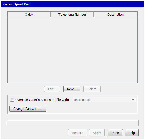
| 4 | Click New to open the Add New Index dialog. |
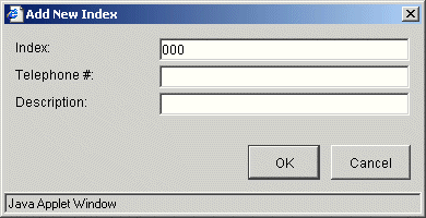
| 5 | Enter the speed dial number in the Index field. |
The Index field is automatically filled in with the next available index number. You can enter any number in the range 000-999.
| 6 | Enter the phone number in the Telephone # field. |
A phone number can be any digit sequence up to 32 digits in length. Be sure to include the external access code if necessary.
Note: Phone numbers for external calls must include the first digit defined in the First Digit Table applet for external dialing access. These external speed dial numbers can be dialed using primary lines, secondary line appearances, and outside lines.
| 7 | Enter a Description for the speed dial number. The description can be any character sequence up to 20 characters in length. |
| 8 | Click OK to close the Add New Index dialog. |
| 9 | Click Apply to save your changes. |
| 10 | Click Done to return to the Management Console. |
Setting the System Speed Dial password
The System Speed Dial password is used when you add a system speed dial number using the phone as described in Adding speed dial numbers using the phone. By default, the system speed dial password is set to 11111.
To set the System Speed Dial password
| 1 | If necessary, click the Administration tab of the Management Console. |
| 2 | Click System Speed Dial, located in the PBX Administration section. |
| 3 | Click Change Password. |
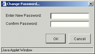
| 4 | Enter a five-digit password in the Enter New Password field. |
| 5 | Enter the password again in the Confirm Password field. |
| 6 | Click OK. |
| 7 | Click Apply to save your changes. |
| 8 | Click Done to return to the Management Console. |
Adding speed dial numbers using the phone
To add a speed dial number using the phone
| 1 | From any Wave phone, dial *88. |
| 2 | Enter the following in sequence: |
| • | 5-digit System Speed Dial password. The default password is 11111. |
| • | 3-digit speed dial index number. You can enter any number in the range 000-999. |
| • | Phone number. A phone number can be any digit sequence up to 32 digits in length. Include the trunk access code (for example, 9) for external calls. |
| 3 | Press # to save the number. |
For example, using the following format:
*88 + [password] + [index] + [phone number] + #
You might enter:
*88 12345 123 914085551212 #
This example creates the system speed dial number “123” that automatically dials 9 for external access and then the number 1-408-555-1212.
| • | If the password you entered is correct, Wave responds with two beeps indicating that the speed dial number was created. The new number overwrites any number previously stored at that index. |
| • | If the password is incorrect, Wave responds with a fast-busy tone. |
A default description is created in Wave’s System Speed Dial table based on the extension number from which the speed dial number was added. After adding a speed dial number using the phone, you can open the System Speed Dial applet to view and edit the default description. See Adding speed dial numbers.
Overriding access profiles when using System Speed Dial
By default, Wave does not override an access profile assigned to a line appearance if its extension does not have permission in its access profile to dial long distance numbers. For example, if an extension’s phone line appearances have Local Only access profiles assigned to them, a user at that extension cannot use any system speed dial numbers that correspond to long distance phone numbers.
If you want users with restrictive access profiles to be able to use system speed dial numbers that require a higher level access profile, you must override the user’s access profile in the System Speed Dial applet.
To override user access profiles when using System Speed Dial
| 1 | If necessary, click the Administration tab of the Management Console. |
| 2 | Click System Speed Dial, located in the PBX Administration section. |
| 3 | Select the Override Caller’s Access Profile checkbox to override a line appearance access profile with the specified access profile when a user dials any system speed dial number on a Wave extension. Select the access profile to use from the drop-down list. |

| 4 | Click Apply to save your change. |
| 5 | Click Done to return to the Management Console. |
Configuring virtual extensions
Configure virtual extensions for users who do not need a physical phone, but require an office extension. These users might be employees who work on the road with a cell phone, but who need to have an office extension listed in the Voicemail Names Directory.
You can configure up to 1024 virtual extensions.
If you configured SIP stations on a system running Wave ISM 1.5 SP2 or earlier. The maximum number of virtual extensions was increased from 500 to 1024 in Wave ISM 1.5 SP2. SIP station IDs are allocated after virtual extensions are. Once you upgrade to Wave ISM 1.5 SP2 or higher, existing SIP station IDs will change, because there are now 1024 ‘preallocated’ virtual extensions, instead of 500. Station IDs are displayed when a user logs on to the User/Group Management applet or ViewPoint. Be sure to make SIP phone users who specify station IDs when logging in, or who have shortcuts that reference station ID aware of this change.
To configure virtual extensions
| 1 | If necessary, click the Administration tab of the Management Console. |
| 2 | Click User/Group Management, located in the PBX Administration section. Log in to the User/Group Management applet when it opens in the remote session window. |
| 3 | Click File > New Userto open the User dialog. |
| 4 | Enter the appropriate name information. |
| 5 | Enter an Extension number. |
| 6 | Under Associated device, use the Slot:port section to select No Slot Selected and No Port Selected from the drop-down lists. |
| 7 | Select Analog from the Telephone type list. |
| 8 | On the User \ External Caller ID tab, select Do Not Send Caller ID. |
| 9 | Configure other options as needed. |
| 10 | Click OK to close the Configure User dialog. |
Configuring zone paging groups
Zone paging groups allow you to page a group of digital phones simultaneously. Zone paging groups are configured in the Zone Paging Groups applet. You can create up to 32 zone paging groups.
SIP paging is integrated into Wave’s zone paging feature. Multicast SIP paging is the preferred method, although both multicast and unicast SIP paging is supported.
|
|
Multicast SIP paging |
Unicast SIP paging |
|
Supported on: |
Edge Gigabit-E IP phones |
Older Edge IP phones |
|
Maximum phones paged simultaneously: |
500 |
150 |
|
Resources required: |
No additional resources required. The page goes out on a single stream to which the phones are subscribed. |
Requires one SIP phone resource per phone. |
To create a zone paging group
| 1 | If necessary, click the Administration tab of the Management Console. |
| 2 | Click Zone Paging Groups , located in the PBX Administration section. |
| 3 | Zone Paging Groups opens listing the zone paging groups created so far. |
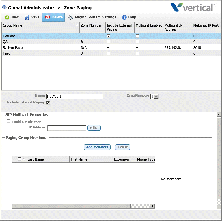
| 4 | Click New on the toolbar to create a new zone paging group. |

| 5 | Enter the following information in the Details section: |

| • | Name. Select a zone number from the drop-down list, or accept the next unassigned zone number that is assigned automatically. |
| • | Zone Number. Enter a descriptive name for the zone paging group. |
| • | Include External Paging. Select this checkbox to also make an overhead page whenever a page is sent to this zone paging group. |
Note: To use this feature, you must have an external paging device on your system, and the Public Address feature must be enabled—see Enabling Public Address. Also, for a digital or SIP phone user to be able to send a page to a zone paging group, you must configure a System Page feature button on that digital phone—see Page feature.)
| 6 | If this zone paging group will be used for SIP multicast SIP paging, select the Enable Multicast checkbox in the SIP Multicast Properties section: |

Accept the default IP Address (if shown), or click Edit to open the the SIP Multicast Properties dialog:
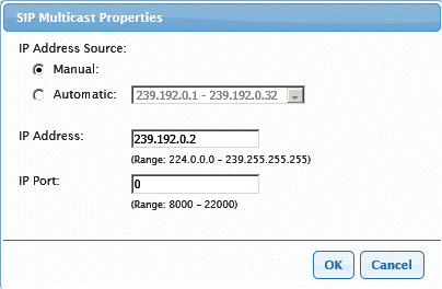
| • | IP Address Source. Do one of the following: |
| • | Click Manual to specify a single IP address to use. If you select Manual, enter that IP Address below. |
| • | Click Automatic to specify a range of IP addresses to use, then select a range from the drop-down list. |
| • | IP Address. (Disabled if you select Automatic.) |
| • | IP Port. |
| 7 | Click Add to add members to the zone paging group. The Add Zone Paging Group Members dialog opens listing the available extensions. |
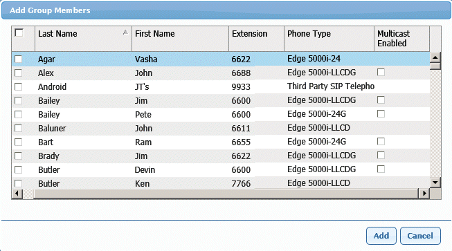
Select one or more members from the list, and then click OK to add them to the group. For SIP phone users, select the Multicast Enabled checkbox.
Note: Only digital and SIP phones appear in the list—analog phones cannot be part of a zone paging group.
| 8 | Click Save on the toolbar to save the new zone paging group. |