Open topic with navigation
1IP Telephony Configuration
The following topics describe how to configure the IP telephony features available on the Wave Server.
Allocating IP telephony resources
Before you configure your system for IP telephony, you must allocate Digital Signaling Processor (DSP) resources that are required for each IP telephony port. For more information about the DSP resources required for IP telephony, refer to “DDSP resources and licensing for IP telephony resources. For general information about managing Wave resources, see Managing Wave system resources.
Note the following:
|
•
|
You must have a SIP Trunk license added on the Wave Server before you can configure SIP trunks. See Chapter 24 for instructions. |
|
•
|
Additional Voice Over IP DSP resources are used only briefly during the life a of a call or while a feature is being used—in this version, you must allocate these resources manually. See Continuing System Administration. |
To allocate IP telephony resources
|
1
|
If necessary, click the Administration tab of the Management Console. |
|
2
|
Click Resource Management, located in the PBX Administration section |
|
3
|
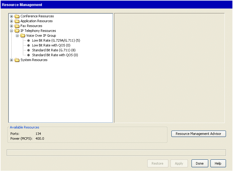
Expand the IP Telephony Resources folder. |
|
4
|
Expand the Voice Over IP Group folder, and select the G.729A/G.711 codec. |
|
5
|
Select the appropriate number of available IP telephony resources in the drop-down list (on the right side of the applet). |
|
6
|
Click Apply to save your changes, and return to the Management Console. |
Configuring site-to-site call routing for IP telephony
You configure call routing in order to use Signaling Control Points for the following outbound call routing scenarios:
|
•
|
Automatic route selection. See Automatic route selection. |
|
•
|
Off-premise extensions. See Off-premise extensions. |
To configure call routing for IP call destinations you will need to perform the following procedures:
Enabling IP telephony or SIP signaling protocols
Perform the following steps to enable the SIP signaling protocol on the Wave Server. Note that you need to do so to use SIP phones with Wave, even if you are not using SIP trunks.
To enable IP telephony or SIP signaling protocols
|
1
|
If necessary, click the Administration tab of the Management Console. |
|
2
|
Click IP Telephony, located in the PBX Administration section. |
|
3
|
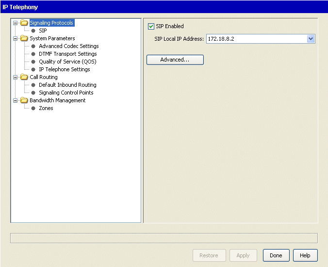
Click SIP from the Signaling Protocols folder in the left pane. |
|
4
|
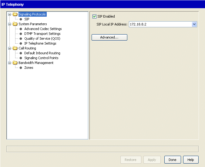
Select the SIP Enabled checkbox. The SIP Local IP Address is selected by default. |
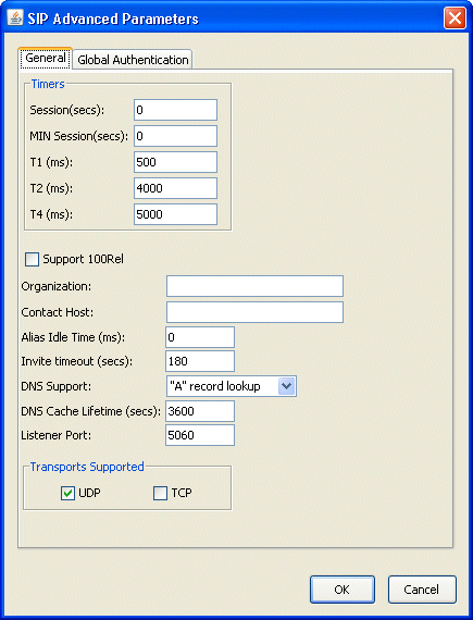
Clicking Advanced opens the SIP Advanced Parameters dialog.
|
•
|
General tab. Use this tab to adjust advanced SIP timers. |
Modifying advanced SIP timers
Important! These are expert settings that should not be modified unless you are directed to do so by your Vertical Technical Support representative. Applying changes that you make to any of the SIP timers on this tab will cause all current SIP calls to be dropped, so be sure to make changes at an appropriate time.
To modify advanced SIP timers
|
1
|
If necessary, click the Administration tab of the Management Console. |
|
2
|
Click IP Telephony, located in the PBX Administration section. |
|
3
|
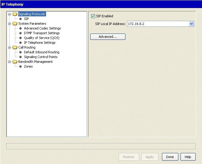
Expand the Signaling Protocols folder in the left pane if necessary, and then click SIP. |
|
4
|
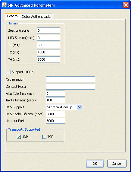
Click Advanced to open the SIP Advanced Parameters dialog. Click the General tab. |
|
•
|
The following SIP Session timers can be used to define keep-alive values for SIP sessions. In Wave, a Session is a SIP call. On long calls, if an endpoint drops off due to a network issue, Wave may think the call is still in progress even though both parties have hung up. |
The default values balance how long you are willing to allow a missing call to go detected without creating too much unnecessary network traffic. You should not modify the default values unless you have identified a specific problem and are instructed to do so by your Wave technical support representative.
|
•
|
Session (secs). Specifies the length of time in seconds after which the endpoint must send a periodic re-INVITE or UPDATE message to Wave. |
|
•
|
MIN Session (secs). Specifies the minimum value Wave will accept from an endpoint for a periodic message to Wave. |
|
•
|
T1 (ms). Specifies the duration (in milliseconds) before the first retransmission of a request over UDP, or an INVITE response over any transport protocol. Subsequent retransmission intervals are calculated by doubling this initial value, up to a maximum value configured in the T2 Timer value. The minimum recommended value is 500ms. Your Vertical Technical Support representative may increase the value of this timer if you are communicating with SIP end points over network connections with longer latencies. |
|
•
|
T2 (ms). Specifies the maximum duration (in milliseconds) before a request is retransmitted over UDP or an INVITE response is retransmitted over any transport protocol. It must be greater than or equal to the value configured in the T1 Timer. The minimum recommended value is 4000ms. |
|
•
|
T4 (ms). Specifies the maximum lifetime of a transaction in the SIP network. After a transaction completes, it is the amount of time that a UAS will retain the transaction information in order to subsume late duplicate responses. |
|
•
|
The following SIP registration expiration timers control the length of time in seconds before a SIP phone or SCP attempts to reregister. Each expiration timer defines a “quiet time” during which the the SIP endpoint (SIP phone or SCP) does not need to be exchanging data with Wave to still be considered “In Service”. An endpoint that goes out of service during the quiet time will not be detected until it fails to complete a registration when the timer expires. Shortening an expiration timer will allow Wave to detect an out-of-service condition sooner, but will increase network traffic. |
The default values balance keeping the endpoint status up to date without creating too much unnecessary network traffic. You should not modify the default values unless you have identified a specific issue with a unique ITSP or third-party phone.
|
•
|
Phone Registration Expires (secs). Specifies the minimum time in seconds within which the phone must send a periodic registration packet to Wave in order for Wave to keep the phone in the “In Service” state. If this timer expires for a particular phone, the phone will be considered “Out of Service”. |
|
•
|
Inbound SCP Registration Expires (secs). Specifies the minimum time in seconds within which the SCP must send a periodic registration packet to Wave in order for Wave to keep the SCP in the “In Service” state. If this timer expires, the SCP will be considered “Out of Service”. |
|
•
|
Outbound SCP Registration Expires (sec). Specifies the minimum time in seconds within which Wave must send a periodic registration packet to the SCP. The SCP may respond to a registration packet with a different timer value, in which case Wave will use the smaller of the two values. If the SCP fails to respond to a registration packet, Wave will place the SCP in the “Out of Service” state and continue to send periodic registration packets to the SCP. If the SCP sends a positive response to a registration packet, Wave will place the SCP in the “In Service” state. |
|
6
|
Click Apply to save your changes. |
Setting up SIP endpoint authentication
Wave supports authentication of inbound requests for SIP endpoints. A SIP endpoint can be either a SIP extension or a SIP Signaling Control Point (SCP). When properly configured, Wave can serve as user agent client (UAC), user agent server (UAS), or a back-to-back user agent (B2BUA) under different call scenarios:
|
•
|
When Wave serves as a UAS or a B2BUA, Wave authenticates and authorizes incoming requests from clients registering to it or wishing to route calls through it. |
|
•
|
When Wave serves as a UAC, it provides appropriate authentication credentials when challenged by the remote UAS. |
Specifically, Wave performs the following SIP endpoint authentication functions:
|
•
|
Authentication of incoming registrations from SIP phones configured as extensions on Wave. |
|
•
|
Authentication of incoming calls from SIP phones configured as extensions on Wave. |
|
•
|
Authentication of outbound registrations for SCPs that are challenged by the remote UAS. |
|
•
|
Authentication of outbound calls through SCPs that are challenged by the remote UAS. |
In very simple terms, registration is the process of assigning an address to a SIP extension or SIP SCP, and authentication is the process of verifying the identity of the SIP extension or SIP SCP before updating the address in the Wave data base.
You set up SIP endpoint authentication parameters in the several places:
|
•
|
To set up global SIP endpoint authentication parameters that are used unless a specific SCP has its own authentication parameters, you use the IP Telephony applet, SIP Advanced Parameters dialog (Global Authentication tab). See Setting up global SIP endpoint authentication parameters. |
|
•
|
To to set up SIP endpoint authentication parameters for a specific SCP, you use the IP Telephony applet, Signaling Control Point dialog (SIP Settings tab). See Configuring Signaling Control Points. |
|
•
|
To specify a user’s SIP endpoint authentication password, you use the User/Group Management applet, User dialog (Phone tab). |
Setting up global SIP endpoint authentication parameters
Perform the following steps to set up global SIP endpoint authentication parameters that are used unless a specific SCP has its own authentication parameters.
Global SIP endpoint authentication best practice
Starting with Wave 4.0, global SIP endpoint authentication will be enabled by default on all new Wave Servers—this will enforce that all SCPs use a password to authenticate unless this option is purposely turned off. (Prior to Wave 4.0, global SIP authentication was disabled by default.)
Important! This change will not be applied to existing Wave Servers that are upgraded to Wave 4.0 or higher. Vertical strongly recommends that global SIP endpoint authentication be enabled on all existing Wave Servers as a standard security measure. You do so in the SCP Settings section in the SIP Advanced Settings dialog, as described below.
To set up global SIP endpoint authentication parameters
|
1
|
If necessary, click the Administration tab of the Management Console. |
|
2
|
Click IP Telephony, located in the PBX Administration section. |
|
3
|
Expand the Signaling Protocols folder in the left pane if necessary, and then click SIP. |
|
4
|
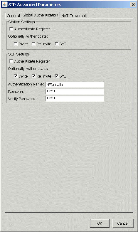
Click Advanced to open the SIP Advanced Parameters dialog. Click the Global Authentication tab. |
|
5
|
Enter the following information in the Station Settings section, based on the level of authentication you require. |
Important! Starting with Wave 4.5, SIP station authentication for Registration and Invites is enabled by default on all Waves as a security measure. All SIP devices have automatically generated SIP authentication credentials assigned. Some third-party SIP phones may not work due to this setting. Vertical strongly advises that you leave these setting enabled at all times.
See your Vertical support representative for more information about how to use these settings.
|
•
|
Optionally Authenticate: |
|
6
|
Enter the following information in the SCP Settings section, based on the level of authentication you require. See your Vertical support representative for more information about how to use these settings. |
|
•
|
Authenticate Register. Starting in Wave 4.0, this option is selected by default on all new Wave Servers. Vertical strongly recommends that global SIP endpoint authentication be enabled on all Wave Servers as a standard security measure. |
|
•
|
Optionally Authenticate: |
|
7
|
For the following fields, enter the authentication credentials provided by the remote SIP endpoint administrator. These three fields are disabled until you select any of the checkboxes in the previous step. These fields are required when they are enabled. |
Note: Starting in Wave 4.0, the default Authentication Name and Password on all new Wave Servers is “TemporaryAuthName” and “TemporaryAuthPassword”.
|
•
|
Authentication Name. 1-32 alphanumeric characters. Authentication name cannot match an existing extension plus last name (for example, “Ryan605”) or another SCP's authentication name. |
|
•
|
Password. 1-48 characters. |
|
8
|
Click Apply to save your changes. |
Configuring Signaling Control Points
You configure a Signaling Control Point (SCP) to determine how to handle IP calls to and from a specific IP address that represents a SIP destination endpoint. The following steps also describe how to configure SIP endpoint authentication settings specific to this SCP.
You can adjust the amount of time that a Signaling Control Point step in an outbound routing table is given to operate before the system tries the next step in the table. See Setting the route step timeout.
Creating a Signaling Control Point
To configure a Signaling Control Point
|
1
|
If necessary, click the Administration tab of the Management Console. |
|
2
|
Click IP Telephony, located in the PBX Administration section. |
|
3
|
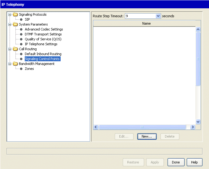
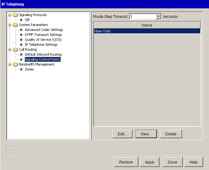
Select Signaling Control Points from the Call Routing folder in the left pane. |
|
4
|
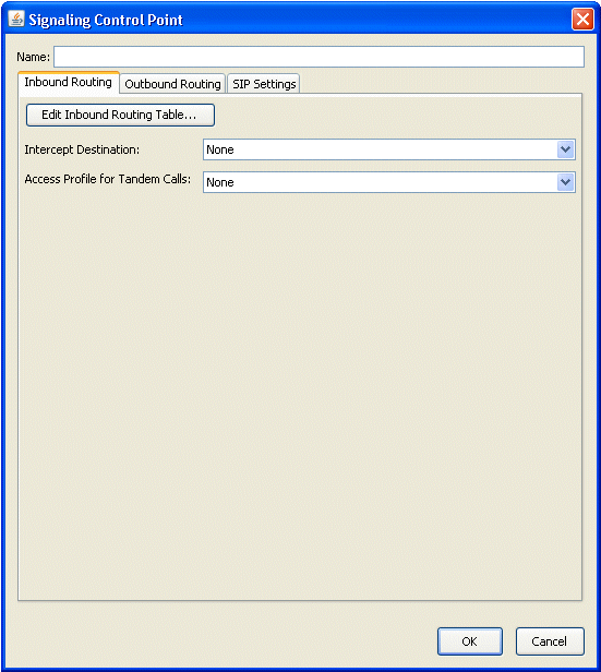
Click New to add a new SCP, or select an existing SCP to edit, then click Edit. The Signaling Control Point dialog opens. |
|
5
|
Enter a Name for the SCP. |
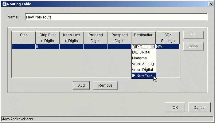
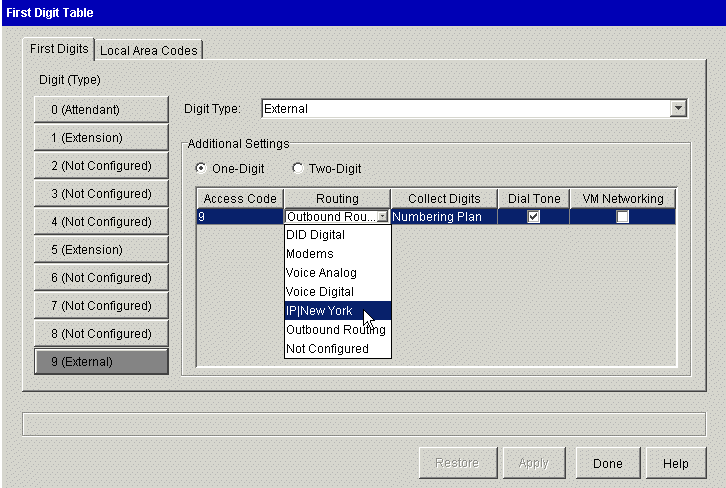
When you configure outbound call routing, this name will appear as IP, a vertical bar (|), and the name you enter here. For example, if you enter New York, it will be displayed as IP|New York in your outbound call routing configuration. See Including Signaling Control Points in the outbound call routing configuration for more information.
Note: The Name field accepts alphanumeric characters as well as the following special characters: ‘ ~ ! # $ % & * ( ) - = + | { } ; : “ , . / < > ?
|
6
|
On the Inbound Routing tab, configure the settings for handling calls received from this SCP. |
|
•
|
Intercept Destination. Select the extension to which calls from this SCP that cannot be matched in the Inbound Routing table will be routed. |
|
•
|
Access Profile for Tandem Calls. Select the access profile to apply to calls received from this SCP that will be connecting to another trunk. (Access profiles identify the different calling privileges that can be associated with extensions, trunk groups, digital connections, and SCPs. See Configuring specific access profiles for more information.) |
Warning! If you have not modified the default “Unrestricted” access profile, be aware that selecting that access profile here could leave your system vulnerable to hackers who are able to identify your Tandem Access Profile number.
|
8
|
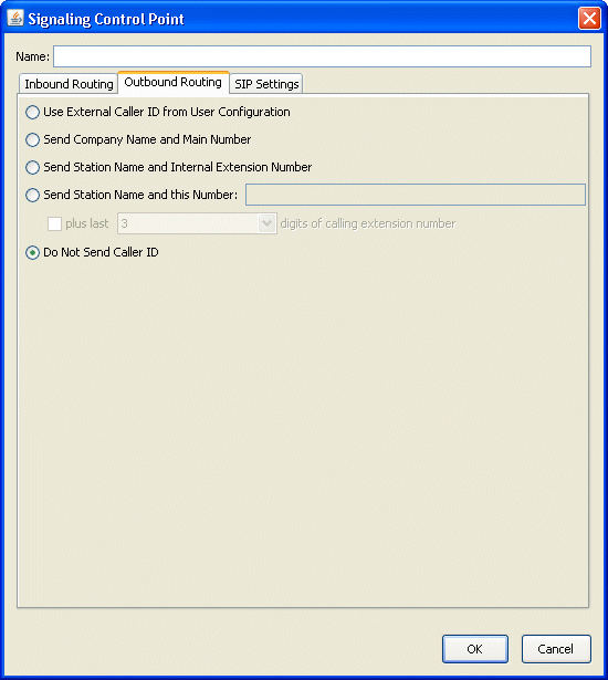
On the Outbound Routing tab, choose one of the Caller ID formats for sending Caller ID with calls to this SCP. (For more about Caller ID, see Configuring Caller ID.) |
|
9
|
On the SIP Settings tab, define authentication and registration settings for this SCP. |
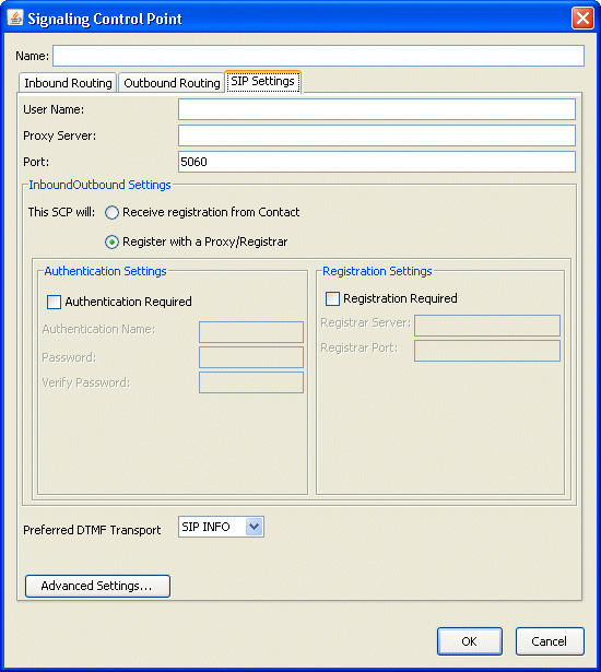
Important! Wave determines the SCP for an incoming call by evaluating User Name, Proxy Server, Port, and Local Listen Port. When configuring SCPs, the combination of these four fields (described below and in step 16) cannot be the same for any two SCPs.
Enter the following information:
|
•
|
User Name. 1-32 alphanumeric character name that identifies this SCP. Each SCP’s user name must be unique and cannot match any user’s extension. This field is only required if registration is required (see step 10). |
|
•
|
Proxy Server. ITSP address, or the address of another Wave Server to or from which this SCP is registering. |
|
•
|
Port. The default port number is 5060. This port is generally used for IP telephony, but if this port is in use in your system, you can specify another port. |
|
10
|
In the Inbound \ Outbound section, specify whether the SIP destination endpoint requires authentication or registration, based on the requirements of your ITSP or SIP trunk provider. Typically, authentication and registration are required for third-party SIP servers. |
|
•
|
This SCP will: The setting you choose here depends on which of the following scenarios applies to you: |
|
•
|
This SCP is connecting to another Wave Server. In a Wave Server-to-Wave Server configuration, you have 2 choices: |
|
•
|
If registration is required between the Wave Servers, select Receive registration from Contact when configuring the SCP on one Server, and Register with a Proxy/Registrar when configuring the SCP on the other Server. It does not matter which setting you select on either Server, as long as the settings are different on each Server. |
|
•
|
If registration is not required between the Wave Servers, select Receive registration from Contact when configuring the SCPs on both Servers, and then select Not Required in step 11. |
Go to step 11.
|
•
|
This SCP is registering to an ITSP. Select Register with a Proxy/Registrar, and go to step 12. |
|
11
|
If you selected Receive registration from Contact in step 10, complete the following two sections: |
|
a
|
In the Authentication Settings section, select one of the following from the Authentication drop-down list: |
|
•
|
Not Required. Select this option if the SIP destination endpoint represented by this SCP does not requires authentication, for example a Wave Server-to-Wave Server configuration where registration is not required. |
|
b
|
In the Registration Settings section, select the Registration Required checkbox if the SIP destination endpoint represented by this SCP requires registration. |
Go to step 13.
|
12
|
If you selected Register with a Proxy/Registrar in step 10, complete the following two sections: |
|
a
|
In the Authentication Settings section, select the Authentication Required checkbox if the destination SIP endpoint requires authentication. |
|
b
|
For the following fields, enter the authentication credentials (Authentication Name and Password) provided by the remote SIP endpoint administrator. These three fields are disabled until you select any of the checkboxes in the previous step. These fields are required when they are enabled. |
|
•
|
Authentication Name. 1-32 alphanumeric characters. Authentication name cannot match an existing extension plus last name (for example, “Ryan605”), another SCP's authentication name, or the SIP global authentication name. |
|
•
|
Password. 1-48 characters. |
Note: The ^ and = special characters are not supported and will be ignored if you enter them in the Password field.
|
c
|
In the Registration Settings section, select the Registration Required checkbox if the SIP destination endpoint requires registration. Then, enter the Registrar Server address and Registrar Port number provided by the remote SIP endpoint administrator. |
|
13
|
Select one of the following from the Preferred DTMF Transport drop-down list, based on the requirements of your ITSP or SIP trunk provider: |
|
•
|
Inband (DTMF digits are left as tones in the original audio stream) |
Note: This setting indicates a preference only - most ITSPs and SIP trunk providers use or prefer RFC 2833. If RFC 2833 is used by your ITSP or SIP trunk provider, Wave will automatically use RFC 2833, no matter what you specify here. On the other hand, if RFC 2833 is not supported by your ITSP or SIP trunk provider, Wave will use the setting that you specify here. If RFC 2833 is not supported by your ITSP or SIP trunk provider, select one of the other settings.
|
14
|
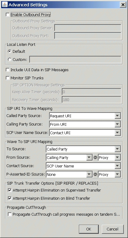
Click Advanced Settings to view or change this SCP’s advanced settings. These settings are primarily used to fine-tune interoperability with ITSPs. |
|
15
|
If this SCP connects to an ITSP that requires that you configure an outbound proxy server, select the Enable Outbound Proxy checkbox and then enter the following information in the Outbound Proxy Settings section. |
|
16
|
The following settings define the default behavior of SIP trunks, and should not be modified unless you are directed to do so by your Vertical support representative. |
|
•
|
Local Listen Port settings |
|
•
|
Include UUI Data in SIP Messages checkbox |
|
•
|
Monitor SIP Trunks checkbox |
|
•
|
SIP OPTION Message Settings
|
|
17
|
The following settings are primarily used to fine-tune interoperability with ITSPs with respect to caller ID. You normally will not need to change the default values unless you are directed to do so by your Vertical support representative working in collaboration with your ITSP to resolve a specific issue. |
Note: Domain source SIP message attribute mapping and P-Asserted-ID options described below may be required to support caller id and privacy related functions on some ITSPs.
|
•
|
SIP URI To Wave Mapping settings: |
|
•
|
Wave To SIP URI Mapping settings: |
|
•
|
From Source ___ @ ___. Select a value from the Source drop-down list, and then select one of the following from the @ drop-down list: |
|
•
|
Proxy. This value represents the Proxy Server setting on the SIP Settings tab of the Signaling Control Point dialog. This is the default value. |
|
•
|
Wave IP. This value represents the SIP Local IP Address. (To view or set this address, in IP Telephony, choose Signaling Protocols > SIP.). |
|
•
|
P-Assisted-ID Source ___ @ ___. Select a value from the P-Assisted ID Source drop-down, and then select one of the following from the @ drop-down list: |
|
•
|
Proxy. This value represents the Proxy Server setting on the SIP Settings tab of the Signaling Control Point dialog. This is the default value. |
|
•
|
Wave IP. This value represents the SIP Local IP Address. (To view or set this address, in IP Telephony, choose Signaling Protocols > SIP.). |
|
18
|
Configure the SIP Trunk Transfer Options [SIP REFER / REPLACES] settings based on your ITSP’s requirements. Select the following checkboxes if your ITSP expects a REFER request for transfers over SIP trunks. When these checkboxes are selected, after the transfer is completed the SIP trunk call is released by Wave. When these checkboxes are not selected, each transferred call uses 2 SIP trunks and Wave maintains control of the call. |
Note: Typically you use the same setting for supervised and blind transfers. These settings are enabled by default.
|
•
|
Attempt Hairpin Elimination on Supervised Transfer. When selected, Wave attempts to eliminate hair-pinning on SIP trunks for supervised transfers. |
|
•
|
Attempt Hairpin Elimination on Blind Transfer. When selected, Wave attempts to eliminate hair-pinning on SIP trunks for blind transfers. |
The following list identifies the settings required by some ITSPs. If you are not sure how to configure these settings, contact your ITSP or Vertical support representative.
|
•
|
Verizon: Select both checkboxes. Test and if transfers over SIP trunks do not work as expected, deselect both checkboxes. |
|
•
|
AccessLine: Dialect both checkboxes. |
|
•
|
Broadvox: Deselect both checkboxes. |
|
•
|
CommPartners: Select both checkboxes. |
|
•
|
Cbeyond: Select both checkboxes. |
|
19
|
To enable propagate progress cut through, select the Propagate CutThrough call progress messages on tandem SIP trunk calls checkbox. |
This option is required to support some ITSPs, and allows in-band call progress tones originating from an ITSP to be received by the calling party on a Wave phone before the call is answered.
|
•
|
If this option is selected, the ITSP provides call progress tones to the calling party. |
|
•
|
If this option is not selected, Wave provides call progress tones. |
If the setting is not correct, the calling party may not receive call progress tones as expected—and won’t be able to tell if the called party is busy or ringing, or experience distorted or intermittent call progress tones.
|
20
|
Click OK to close the Advanced Settings dialog. |
|
21
|
Click OK to add the SCP to the table. |
|
22
|
Click Apply to save your changes. |
Setting the route step timeout
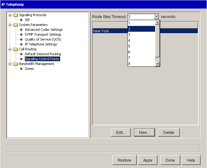
You can adjust the amount of time that a Signaling Control Point step in an outbound routing table is given to operate before the system tries the next step in the table. Increasing this timeout (the maximum is 30 seconds) will help allow for network or other delays.
To set the Signaling Control Point route step timeout
|
1
|
If necessary, click the Administration tab of the Management Console. |
|
2
|
Click IP Telephony, located in the PBX Administration section. |
|
3
|
Select Signaling Control Points from the Call Routing folder. |
|
4
|
In the Route Step Timeout drop-down list, select the number of seconds before the system times out and tries the next step in an outbound call routing table. |
Configuring default inbound IP call routing
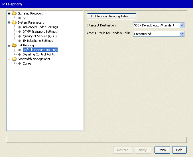
To specify how to route incoming IP calls from unknown sources (that is, sources that are not included in your list of Signaling Control Points), configure the call handling rules with the default inbound call routing settings.
To configure default inbound IP call routing
|
1
|
If necessary, click the Administration tab of the Management Console. |
|
2
|
Click IP Telephony, located in the PBX Administration section. |
|
3
|
Select Default Inbound Routing from the Call Routing folder. |
|
4
|
Click Edit Inbound Routing Table to specify the call sources, schedules, and routing. |
For more information about editing the Inbound Routing Table, see Configuring inbound routing tables.
Note: If you want to route all incoming calls as received, there is no need to edit the inbound routing table. Only edit the inbound routing table if you want to route by schedule or do inbound digit translation.
|
5
|
Choose an extension from the Intercept Destination drop-down list. |
|
6
|
Select an access profile in the Access Profile for Tandem Calls drop-down list. |
|
7
|
Click Apply to save your changes. |
Including Signaling Control Points in the outbound call routing configuration
To route outbound calls to IP call destinations, select Signaling Control Points instead of trunk groups in your outbound call routing configuration.
To include Signaling Control Points in outbound call routing
While you are configuring your outbound call routing, select a Signaling Control Point from the Destination drop-down list at the point when a trunk group might be selected.
The following graphic shows an example of configuring an outbound routing table in the Outbound Routing applet:
The following graphic shows an example of configuring the External digit in the First Digit Table:
Configuring IP phones
This section provides instructions on configuring the desktop, wireless and software IP phones certified for use with the Wave system. The procedures assume you are already familiar with configuring Wave digital phones, and only address the steps specific to configuring IP phone options.
IP phones require the ability to log into and download files from the Wave FTP or TFTP server. Any network configurations that do not allow that connectivity will result in the IP phones being unable to initialize. These configuration areas include, but are not limited to, the following:
|
•
|
Internal firewalls, such as Check Point FireWall-1 |
|
•
|
RRAS address / port filtering |
|
•
|
TFTP/FTP directory security |
IP phone configuration includes the following:
Configuring IP phone extensions
This procedure assumes you are already familiar with configuring Wave phone extensions, and only addresses configuration tasks specific to configuring IP phone extensions.
To configure IP phone extensions
|
1
|
If necessary, click the Administration tab of the Management Console. |
|
2
|
Click User/Group Management, located in the PBX Administration section. The User/Group Management applet opens, with the Users view showing. |
|
3
|
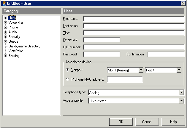
Double-click the user to whom you want to assign a IP phone extension, or create a new IP phone user. The User dialog opens. |
|
4
|
Click IP phone MAC Address field, and then enter the phone’s MAC address. The phone’s MAC address can be found on the phone itself, on the box the phone came in, or via the phone’s options menu. |
|
5
|
Choose the appropriate Telephone type from the drop-down list. Do one of the following: |
|
•
|
For a Vertical-branded IP phone, select the appropriate model. |
|
•
|
For a third-party SIP phone device (for example, a Counterpath IP softphone), select IP third party SIP Telephone. |
|
6
|
Click OK to save the settings. |
|
•
|
If you are configuring Vertical-branded IP phones, go to the next section. |
|
•
|
If you are configuring a third-party IP phone device, see the documentation that came with the device for additional configuration requirements. |
Configuring Vertical-branded IP phones
The configuration process for Vertical-branded IP phones is similar to that of digital phones, as described in About phone templates. This section describes the following additional configuration tasks specific to Vertical branded IP phones. For tasks that apply to your configuration, perform the indicated steps at each Vertical-branded IP phone. Be sure to follow the steps for your specific phone model.
Configuring a static IP address for Vertical-branded IP phones
This task is optional, depending on how you want to assign an IP address to a Vertical-branded IP phone.
|
•
|
If you want to assign a static IP address to the phone, perform the steps below on all Vertical branded IP phones. Be sure to perform the steps specific to your phone model. |
|
1
|
To configure a static IP address on a Vertical-branded 9133i, 9112i, 480i, or 480i/CT IP phone: |
|
a
|
Press the Options button. |
|
b
|
Select Network Settings from the main menu. When prompted, enter the password (the default password is 22222.) |
|
2
|
To configure a static IP address on a Vertical-branded 53i, 55i, or 57i IP phone: |
|
a
|
Press the Options button. |
|
b
|
Select Administrator Menu. When prompted, enter the admin password (the default password is 22222.) |
|
c
|
Select Network Settings > DHCP Settings. |
|
3
|
Select DHCP > Use DHCP? |
|
4
|
Select No, and then press Done. |
|
5
|
Select and configure the settings for the phone’s IP address, Subnet Mask, and Gateway. |
Configuring the TFTP server to synchronize Vertical-branded IP phones with the Wave Server
This task is required. You must perform the following steps on all Vertical branded IP phones. Be sure to perform the steps specific to your phone model.
|
1
|
To configure the TFTP server on a Vertical-branded 9133i, 9112i, 480i, or 480i (CT) IP phone: |
|
a
|
Press the Options button. |
|
b
|
Select Network Settings from the main menu. When prompted, enter the password (the default password is 22222.) |
|
c
|
Select the TFTP server options, and then select TFTP Server > Primary TFTP. |
|
2
|
To configure the TFTP server on a Vertical-branded 53i, 55i, and 57i IP phone: |
|
a
|
Press the Options button. |
|
b
|
Select Administrator Menu. When prompted, enter the admin password (the default password is 22222.) |
|
c
|
Select the TFTP server options, and then select TFTP Server > Primary TFTP. |
|
3
|
Enter the VAM IP address on the Wave Server. (The factory-default VAM IP address is 192.168.205.1.) |
|
4
|
Press Done (or Cancel). Continue pressing Done until you are asked to restart the phone, and then confirm the phone restart. If you are not prompted to restart the phone, manually restart the phone by pressing the Options menu and then selecting Phone Status > Restart Phone. |
Note: The phone may take several minutes to download required configuration files, and restart automatically one or more times depending on which files are required.
Setting date and time on Vertical-branded IP phones
This task is optional. By default, after a IP phone downloads the configuration file the date and time displayed on the phone is set to the physical location of the Wave Server server. If the IP phone is in a different time zone than the Wave server, the phone's date and time may not match the user's location. This section describes how to adjust the date and time displayed on the phone.
To set date and time
|
1
|
Press the Options button. |
|
2
|
Scroll to Date and Time and press Show. |
|
3
|
Select Time Server and press Show. Enter the IP address of the Wave Server, and then press Done. |
|
4
|
Select Set Time and press Show. Enter the current time, and then press Done. |
|
5
|
Select Time Format and press Show. Select either 12h or 24h, and then press Done. |
|
6
|
Select Set Date and press Show. Enter current date, and then press Done. |
|
7
|
Select Date Format and press Show. Select the preferred date style, and then press Done. |
|
8
|
Select Time Zone and press Show. Select your time zone, and then press Done. |
|
9
|
Select Daylight Savings and press Show. Select the correct daylight savings time setting, and then press Done. |
|
10
|
When the Date and Time settings are complete, press Done. |
Setting up OpenVPN Server for a Wave Gigabit-E IP phone user
See Using OpenVPN Server.
Setting up NAT traversal for a remote user
See Configuring NAT traversal .
Enabling IP call bandwidth
IP phones cannot make external calls until the bandwidth is allocated for them. To do this, configure the Home bandwidth management zone in Configuring the home zone.
Changing the password for the IPPhone user account
The IPPhone account is not used unless FTP access required. For security reasons, Vertical Communications recommends that you change the password for the IPPhone user account from the default password of Vertical4VoIP!
To change the password for the IPPhone user account
|
1
|
Log on to the Management Console. |
|
2
|
Open the Password Administration applet. |
|
3
|
In the Password Administration dialog, click the IPPhone user account and click Edit. |
|
4
|
Enter the new password in the Password and Confirm Password fields. |
Configuring bandwidth management zones
Configure the home, remote and default remote zones using the procedures in this section. For information about the bandwidth management zones, see Bandwidth management.
Review the following topics to configure bandwidth management zones
Zone configuration recommendations
Keep in mind the following rules while configuring bandwidth management zones:
|
•
|
A bandwidth management zone is defined by a set of IP address ranges. Any number of Signaling Control Points (SCPs) and IP phones can exist in the same zone. Any SCP or IP phone whose IP address is not explicitly configured as part of a zone is automatically included in the Default Zone. All TDM devices, including voicemail ports and conference bridges reside in the Home Zone. |
|
•
|
For devices in two different bandwidth management zones to be able to communicate, it is necessary that a common codec is configured in each of the zones’ inter-zone preference lists. In the absence of a common codec, calls between the two zones will not be allowed. |
|
•
|
Calls between bandwidth management zones always engage the inter-zone rules for both zones. |
|
•
|
When an IP device is involved in a conference, the inter-zone rules between the IP device’s zone and the Home Zone come into play. If there are no common codecs, or there is insufficient bandwidth, then the device is not permitted to participate in the conference. |
Codec configuration guidelines
With the rules listed in Zone configuration recommendations in mind, Vertical recommends that you follow these configuration guidelines:
|
•
|
Configure all zones to use the G.711U codec only (either u-law, a-law, or both), and remove the G.729 codec from the inter-zone codec preference lists. If G.729 or G.711A is specifically required in your implementation, use then that codec only and leave all other codecs off the preference lists. |
|
•
|
If there is a zone requiring G.729 exclusively, then G.711 should be left off of its inter-zone preference list. In this situation, it is essential that all remaining zones include G.729 on their inter-zone codec preference lists. Devices in zones configured to use G.711 exclusively will not be able to call devices in zones configured to use G.729 exclusively. |
Codec negotiation
Wave chooses a codec based on the following rules:
|
•
|
All codecs not supported by both endpoints are filtered out. |
|
•
|
The remaining codecs are scored based on their positions in the preference lists (for example, if G.711 is first on one list and third on the other, its score is 4). |
|
•
|
Wave chooses the codec with the lowest score. |
|
•
|
If two codecs have the same score, Wave prioritizes lower bandwidth over voice quality. |
|
•
|
If G.711 Mu-Law and G.711 A-Law tie for the lowest score, Wave uses Mu-Law. |
Configuring the home zone
To configure the home zone
|
1
|
If necessary, click the Administration tab of the Management Console. |
|
2
|
Click IP Telephony, located in the PBX Administration section. |
|
3
|
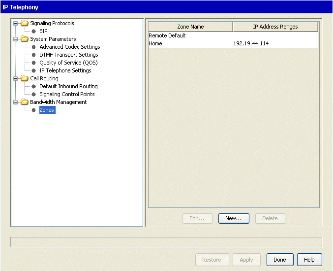
Select Zones from the Bandwidth Management folder. |
|
4
|
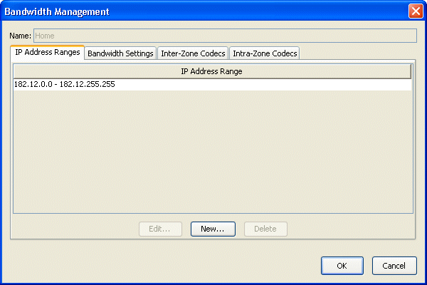
Select Home from the table, and click Edit. |
|
5
|
Configure the IP address range. |
Include all the applicable IP address ranges used by the IP phones on the local Wave system. The Home Zone always includes the IP address of the Wave for bandwidth and call control purposes, whether or not it is explicitly specified in the IP Telephony applet.
To add an IP address range:
|
a
|
Select thIP Address Ranges tab. |
|
b
|
Select the IP address range and click Edit to alter the existing range, or click New to add a new IP address range. |
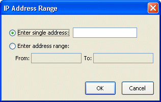
You can also add single IP addresses.
|
6
|
Click the Bandwidth Settings tab. |
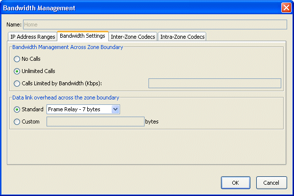
|
a
|
Select a Bandwidth Management Across Zone Boundary setting. |
|
•
|
No Calls. No calls are allowed to IP addresses outside the ranges defined in this zone. |
|
•
|
Unlimited Calls. All calls to or from all IP addresses are allowed. |
|
•
|
Calls Limited by Bandwidth (Kbps). Calls placed to or received from IP addresses outside this zone are limited to the number that can be supported by the bandwidth specified here. |
|
b
|
Select a Data link overhead across the zone boundary setting. |
|
•
|
Standard. Select one of the standard data links from the drop-down list. The option you select determines the amount of overhead the system adds to the bandwidth when calls cross the zone boundary. Specifying enough overhead is important in preventing too many calls from being placed over the WAN link; if the transport overhead is not included, then more calls would be allowed than the link could support. |
Note: Be sure to use the option that most accurately reflects the type of data link used in this zone. If you need to use a different value than those provided, enter the value in the Custom ___ bytes field, described below.
|
•
|
Custom ___ bytes. Enter a custom data link overhead in the field provided. |
Note: This helps the Wave system calculate Inter-zone bandwidth availability for IP calls. This setting must be changed if the physical data link type across this zone is changed.
|
7
|
Click the Inter-Zone Codecs tab. |
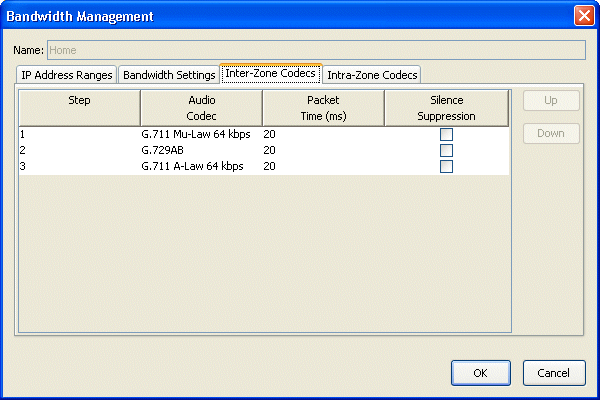
The default codecs are displayed in a table. Depending on your ITSP’s specific requirements, you may need to change the default settings for a codec, add or remove a codec, and so forth.
|
a
|
To change the default settings for a codec: |
|
•
|
Packet Time (ms). Click in this column for the codec and then select the value to use from the drop-down list. |
Note: This setting indicates a preference only, and may be overridden automatically depending on other factors. For example, if more than 48 channels are configured on the Wave Server base unit, or more than 64 channels are configured on a Media Resource Module (MRM), a packet time of 30 ms will be used to support the total number of channels, regardless of what value you specify here.
|
•
|
Select or deselect the Silence Suppression checkbox for the codec to enable or disable silence suppression. |
|
b
|
To add a codec, click Add. A new entry is added at the bottom of the table. Specify the following: |
|
•
|
Audio Codec. Click in this column and then select an available codec name to add from the drop-down list. |
See step 7a for more about the following settings:
|
c
|
To change a codec’s position in the list, select it and then click Up or Down. |
|
d
|
To remove a codec from the list, select it, and then click Remove. |
|
8
|
Click the Intra-Zone Codecs tab. To define intra-zone codec behavior, see step 7 for actions you can perform here. |
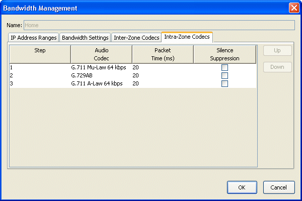
|
9
|
Click OK to close the Bandwidth Management dialog. |
|
10
|
Click Apply to save the Home zone configuration. |
Configuring remote zones
To configure remote zones
|
1
|
If necessary, click the Administration tab of the Management Console. |
|
2
|
Click IP Telephony, located in the PBX Administration section. |
|
3
|
Select Zones from the Bandwidth Management folder. |
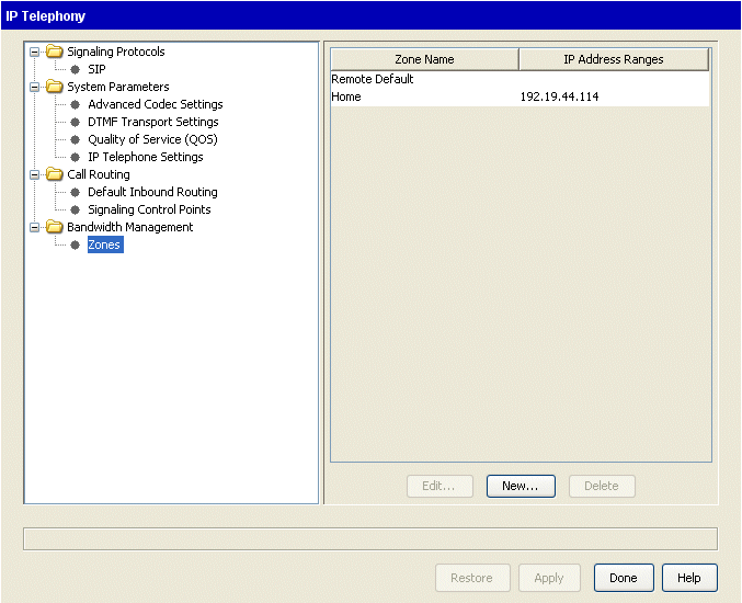
|
4
|
Click New to open the Bandwidth Management dialog. |
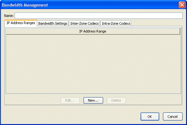
|
5
|
Enter a Name for the zone. |
|
6
|
Configure the IP address ranges, bandwidth settings, inter-zone codecs, and intra-zone codecs as explained in Configuring the home zone. |
|
7
|
Click OK to close the Bandwidth Management dialog. The new zone is displayed in the list. |
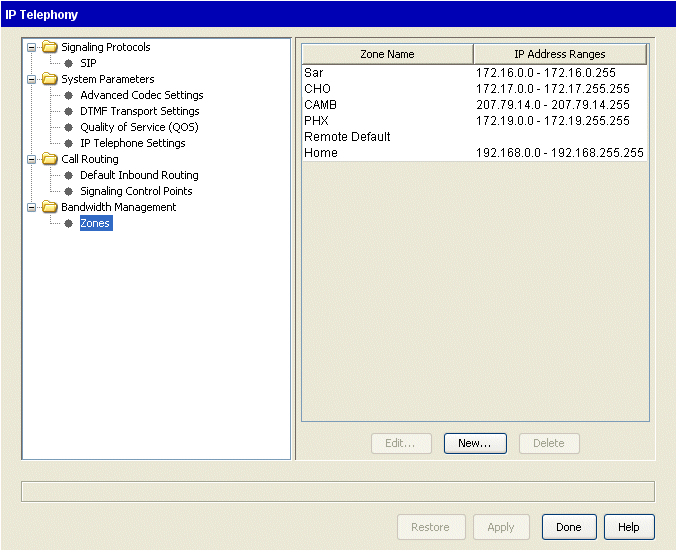
|
8
|
Click Apply to save the new remote zone configuration. |
Configuring the remote default zone
To configure the remote default zone
|
1
|
If necessary, click the Administration tab of the Management Console. |
|
2
|
Click IP Telephony, located in the PBX Administration section. |
|
3
|
Select Zones from the Bandwidth Management folder. |
|
4
|
Select Remote Default from the table, and click Edit. |
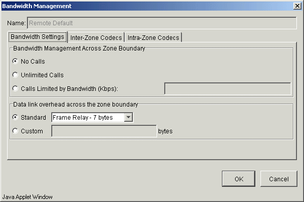
Note: For security reasons the default Bandwidth Management Across Zone Boundary setting is No Calls.
Note: You do not configure IP address ranges in the Remote Default zone configuration because this zone is used to manage bandwidth for all calls from IP addresses not defined in any of your configured zones.
|
6
|
Click OK to close the Bandwidth Management dialog. |
|
7
|
Click Apply to save the remote zone configuration changes. |
Configuring music on hold for IP calls
To configure music on hold for IP calls, perform the following tasks:
|
•
|
Allocate low bit rate music on hold resources. Low Bit Rate (G.729A/G.711) music on hold resources are required if IP calls are expected to use the G.729 codec. If IP calls are expected to use the G.729 codec and no low bit rate resources are allocated for music on hold, IP callers on hold will hear silence instead of music |
To allocate low bit rate music on hold resources, use the Resource Management applet or Resource Management Advisor as described in Using Resource Management and Resource Management Advisor.
|
•
|
Configure a system port for music on hold and enable system-wide music on hold. See Configuring Music On Hold. Be sure to select the Support IP Music On Hold checkbox when you enable system-wide music on hold. |
Adjusting IP call quality parameters
Caution! These parameters only apply to the IP telephony resources on the Wave system and do not affect the performance of the IP phones. These are expert settings that should not be modified unless you are instructed to do so by your Vertical Technical Support representative.
Most of the IP call quality parameters can be found in thSystem Parameters folder of the IP Telephony applet. If you are not familiar with IP telephony, you should contact your Wave product support vendor for information about adjusting these settings. If you want to return to the system defaults, click Restore Defaults in any of the System Parameters screens.
You can adjust the following IP call quality parameters:
Jitter buffer
Caution! This is an expert setting that should not be modified unless you are instructed to do so by your Vertical Technical Support representative.
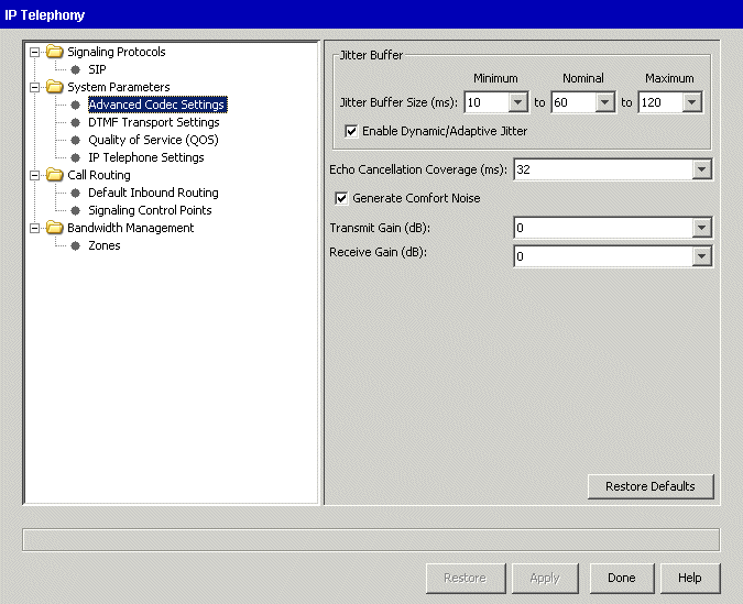
Voice packets can experience a high level of network delay, especially if the lines are congested. The jitter buffer temporarily holds incoming packets in order to assemble them in the correct order and recreate a high-quality voice signal.
To adjust the jitter buffer
|
1
|
If necessary, click the Administration tab of the Management Console. |
|
2
|
Click IP Telephony, located in the PBX Administration section. |
|
3
|
In the left pane, expand System Parameters and then select Advanced Codec Settings. |
|
4
|
Specify the range of acceptable delay in the Jitter Buffer Size drop-down lists. |
|
5
|
Select the Enable Dynamic/Adaptive Jitter checkbox (this is the default setting). |
The Dynamic/Adaptive Jitter feature optimizes the jitter buffer based on voice traffic and network conditions. If you disable this feature, Wave adheres to the values in the Nominal and Maximum fields.
Echo cancellation
Caution! This is an expert setting that should not be modified unless you are instructed to do so by your Vertical Technical Support representative.
Echo in a phone network is caused by signal reflections generated by the hybrid circuit that converts between a 4-wire circuit (a separate transmit and receive pair) and a 2-wire circuit (a single transmit and receive pair). Echo is present even in a conventional circuit switched phone network. However, it is acceptable because the round trip delays through the network are smaller than 5 ms and the echo is masked by the normal side tone every phone generates.
Perceived echo becomes a problem in packet-switched networks because the round trip delay through the network is almost always greater than 5 ms. Thus, echo cancellation techniques are often used.
Echo is generated toward the packet-switched network from the TDM phone network. The echo canceller compares the voice data received from the packet-switched network with voice data being transmitted to the packet-switched network. The echo from the phone network hybrid is removed by a digital filter on the transmit path into the packet-switched network.
To adjust the echo cancellation settings
|
1
|
If necessary, click the Administration tab of the Management Console. |
|
2
|
Click IP Telephony, located in the PBX Administration section. |
|
3
|
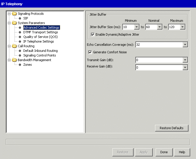
In the left pane, expand System Parameters and then select Advanced Codec Settings. |
|
4
|
Select a value from the Echo Cancellation Coverage drop-down list. |
Note: The recommended value (and default) is 32 ms.
Comfort noise
Caution! This is an expert setting that should not be modified unless you are instructed to do so by your Vertical Technical Support representative.
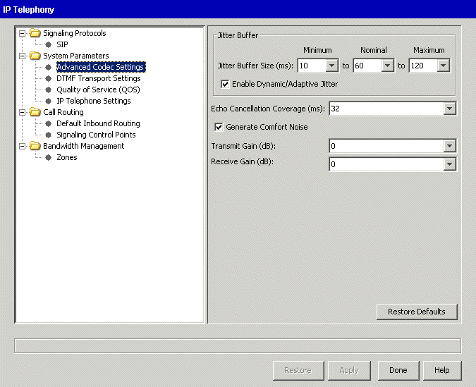
This option generates comfort noise during silences on the receiving end of the phone call in calls where silence suppression is enabled. Comfort noise is white noise that masks “dead” time in a phone conversation. Use this option to simulate a circuit-switched phone conversation. This option is enabled by default.
To adjust the comfort noise settings
|
1
|
If necessary, click the Administration tab of the Management Console. |
|
2
|
Click IP Telephony, located in the PBX Administration section. |
|
3
|
In the left pane, expand System Parameters and then Select Advanced Codec Settings. |
|
4
|
Select the Generate Comfort Noise checkbox if you want the Wave Server to automatically generate background noise. |
Gain
Caution! This is an expert setting that should not be modified unless you are instructed to do so by your Vertical Technical Support representative.
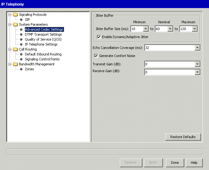
The gain settings adjust the transmit gain and receive gain levels for the TDM segment of a call.
The following diagram shows transmit and receive gain:

To adjust the transmit and receive gain values
|
1
|
If necessary, click the Administration tab of the Management Console. |
|
2
|
Click IP Telephony, located in the PBX Administration section. |
|
3
|
In the left pane, expand System Parameters and then select Advanced Codec Settings. |
|
4
|
Adjust the following values. |
|
•
|
Transmit Gain. If the volume level to the TDM phone is too low, you can increase the transmit gain. |
|
•
|
Receive Gain. If the volume level from the TDM phone is too low, you can increase the receive gain. |
DTMF transport settings
Caution! The default values in this pane will work for most VoIP networks. These are expert settings that should not be modified unless you are instructed to do so by your Vertical Technical Support representative to address specific VoIP network requirements or issues.
To configure the DTMF transport settings
|
1
|
If necessary, click the Administration tab of the Management Console. |
|
2
|
Click IP Telephony, located in the PBX Administration section. |
|
3
|
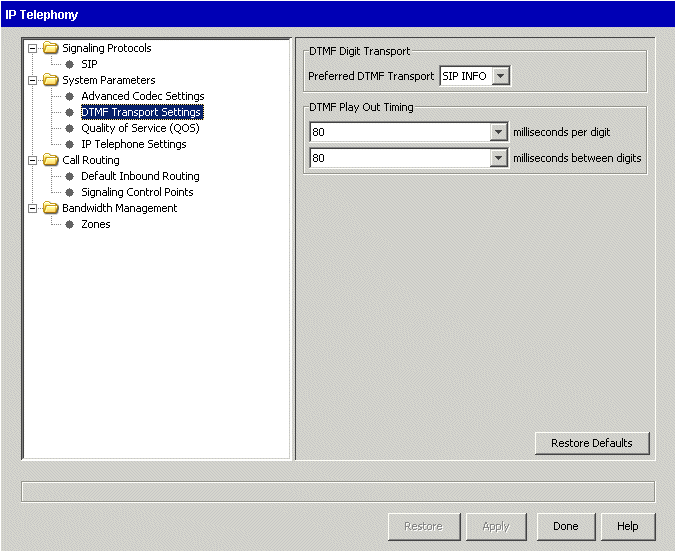
In the left pane, expand System Parameters and then select DTMF Transport Settings. |
|
4
|
In the DTMF Digit Transport section, select one of the following from the Preferred DTMF Transport drop-down list, based on the requirements of your ITSP or SIP trunk provider. |
|
•
|
Inband (DTMF digits are left as tones in the original audio stream) |
Note: This setting indicates a preference only - most ITSPs and SIP trunk providers use or prefer RFC 2833. If RFC 2833 is used by your ITSP or SIP trunk provider, Wave will automatically use RFC 2833, no matter what you specify here. On the other hand, if RFC 2833 is not supported by your ITSP or SIP trunk provider, Wave will use the setting that you specify.
|
5
|
In the DTMF Play Out Timing section, specify the following play out times in milliseconds: |
|
•
|
___ millisconds per digit. Length of time that each DTMF digit plays. |
|
•
|
___ milliseconds between digits. Length of time between each DTMF digit. |
Quality Of Service (QoS) settings
Caution! These are expert settings that should not be modified unless you are instructed to do so by your Vertical Technical Support representative.
Note: At least one Media Resource Module (MRM) is required on the Wave Server if you plan to use Quality of Service (QoS) settings with IP resources for VoIP calls. Contact your Wave provider for more information.
To configure the Quality of Service (QoS) settings
|
1
|
If necessary, click the Administration tab of the Management Console. |
|
2
|
Click IP Telephony, located in the PBX Administration section. |
|
3
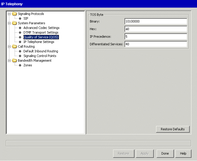
|
In the left pane, expand System Parameters and then click Quality of Service (QOS). |
|
4
|
In the TOS Byte section, specify a value for one of the parameters. Changing the value in any of these fields adjusts the other fields to display equivalent values. |
Note: Make a note of these values if you are connecting the Wave Server to an external router because you will need to specify these values when you configure prioritization of voice frames in the router.
Configuring NAT traversal
NAT traversal is one method to enhance remote phone integration. NAT traversal is less secure than Wave OpenVPN Server, the preferred method, but is supported on all Vertical Edge SIP phones. (For more about Wave OpenVPN Server, see IP Telephony Configuration.
NAT traversal is a way to establish and maintain IP connections that traverse network address translation (NAT) gateways. NAT provides automated translation of IP addresses between different networks. For example, a company might use private IP addresses on a LAN that are represented by a single IP address on the WAN side of their router.
Configuring NAT traversal consists of the following tasks in the following order:
|
•
|
Configuring the Wave Server, including enabling NAT traversal, specifying the STUN servers to use, and configuring the SCP. These steps are described below. |
|
•
|
Configuring remote users for NAT traversal. You do so on a per-user basis via User/Group Management. See The Phone \ Networking tab |
|
•
|
Configuring your router for NAT traversal. NAT traversal has been tested with two industry-leading routers: |
|
•
|
Dell Sonicwall TZ 215-series router |
Other routers may work successfully, but Vertical cannot provide configuration details for all brands.
See Configuring the SonicWALL TZ215 Router for NAT Traversal or Configuring the Cisco 881 Router for NAT Traversal for detailed router configuration steps.
Configuring the Wave Server: Enabling NAT traversal and specifying STUN servers to use
Session Traversal Utilities for NAT (STUN) is a public service that is used to aid a phone or phone system in properly routing signaling so a call is successful and audio is present. A STUN server allows NAT clients (for example (for example a Wave Server behind a firewall) to set up phone calls to a VoIP provider hosted outside of the local Wave network.
When you deploy NAT traversal, best practice is to specify more than one STUN server:
|
•
|
At least one STUN server must be specified for auto discovery to work. |
|
•
|
Typically a minimum of two STUN servers are specified to provide some level of fault tolerance. |
|
•
|
You can specify up to 3 STUN Servers. |
To enable NAT traversal and specify STUN servers
|
1
|
If necessary, click the Administration tab of the Management Console. |
|
2
|
Click IP Telephony, located in the PBX Administration section. |
|
3
|
In the left pane, select Signaling Protocols, and then click Advanced in the right pane. |

|
4
|
On the NAT Traversal tab, select the following options: |
|
•
|
Enable NAT Traversal Support
|
|
•
|
Auto discover Wave global addresses using STUN
|
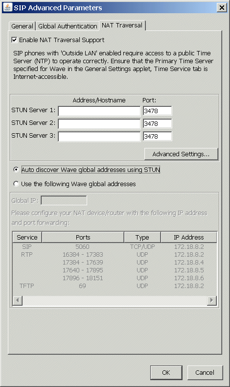
You typically do not need to change the default STUN advanced settings.
|
5
|
For STUN Server 1, STUN Server 2, and STUN Server 3, enter the IP address or hostname of each STUN server you are using. |
Important! Note the table at the bottom of the SIP Advanced Parameters dialog on the previous page that lists the RTP port ranges and IP addresses used by each of the SIP endpoints on the Wave Server—the VAM and three MRM DSPs. You will use the IP address and port range information listed here when you configure your router for NAT traversal, as described in the configuration guide for your router. In this example, the four RTP services listed are for (in top-down order) the VAM, MRMA, MRMB, and MRMC.
To configure the SCP for NAT traversal
|
7
|
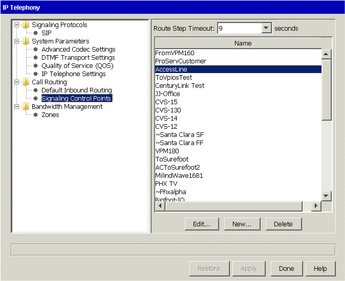
Expand Call Routing in the left pane, and then select Signaling Control Points. |
|
8
|
Select your ITSP’s SCP and then click Edit. |
|
9
|
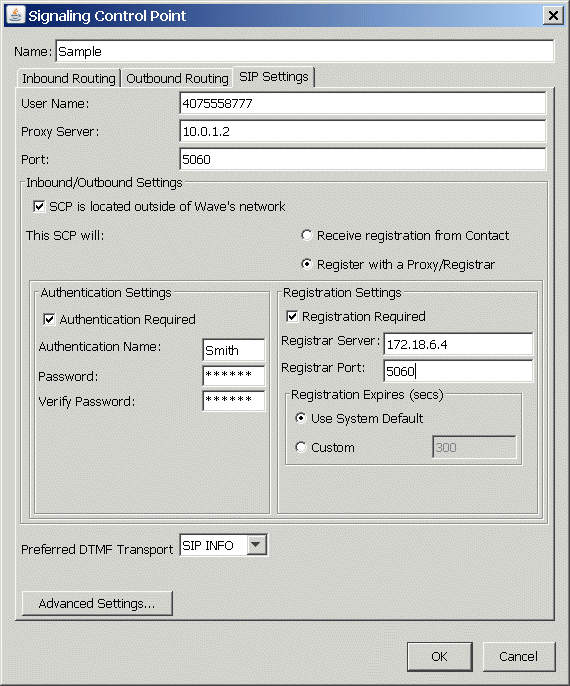
Click the SIP Settings tab. In the Inbound/Outbound Settings section, select SCP is located outside of Wave’s network. |
|
10
|
Click OK, and then exit IP Telephony. |
How IP telephony ports are used
When using VoIP in a network, especially one that includes a firewall, you need to know the ports used by the packets that carry VoIP traffic. The following table lists these ports.
|
|
|
RTP
|
UDP/dynamic (16384 - 18384) - not configurable
|
UDP/Dependant on other endpoint
|
|
RTCP
|
UDP/dynamic (16385 - 16835) - not configurable
|
UDP/Dependant on other endpoint
|
|
|
|
|
5060 - configurable to 5061
|
5060, 5061
|
|
|
UDP 65000 (used for music on hold)
|
|


